2787-2147 (/0000-00x0)
Installation and Removal
Product manual | Version: 1.2.2
31
Power Supply Pro 2
6
Installation and Removal
!
NOTICE
Avoid electrostatic discharge!
The products are equipped with electronic components that you may destroy by electro-
static discharge when you touch. Please observe the safety precautions against electro-
static discharge in accordance with EN 61340-5-1/-3. Pay attention while handling the
products to good grounding of the environment (persons, job and packing).
!
NOTICE
Do not cover the ventilation openings!
To ensure adequate air circulation, the ventilation openings must be kept clear. Maintain
a distance of at least 50 mm from the ventilation openings to adjacent surfaces.
The letters shown in parentheses refer to positions in the “View” figure in section View.
Mounting Positions
• Nominal mounting position (see also figure under View): Front side facing forwards,
marking legible, and bottom ventilation openings facing upwards and downwards.
• Never operate the product directly next to other components!
Table 43: Minimum Clearances
Installation Clearances
Clearance
Passive adjacent device
(adjacent device does not generate heat)
Above/below
50 mm
On side
6 mm
Active adjacent device
(adjacent device generates additional heat; equivalent product un-
der full load)
Above/below
50 mm
On side
12 mm
DIN-35 Rail
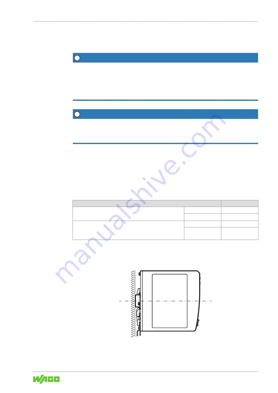
The DIN-35 rail is located in the center of the vertical axis (height) of the product (see
section
8
Figure 14: Position of the DIN-35 rail
The distances from the central axis of the DIN-35 rail to the top and bottom are 65 mm.

