background image

2787-2344 (/0000-00x0)

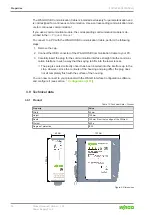
Properties

14

Product manual | Version: 1.0.1
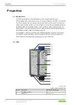
Power Supply Pro 2

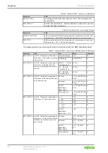
Position

Comment

For Details, See Section

8

Additional technical data

8


Technical data [

}

 18]

9

Information on the instruction leaflet

10

Field for guidelines, approvals and standards

8


Guidelines, approvals and stan-

dards [

}

 24]

11

Label with product-specific information

Label

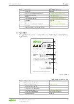
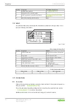
3.4 Label

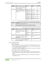
An additional label with product-specific information is attached to the type label. It con-
tains the following information:

SN: (37S)

UN315640102

27872344
0101010000005001

1320    01   01   01

0

0

_

4

4 1

-

0

0

0

6

-

5

0

-

1

1

1

2
3

4

5

6

7

Figure 3: Label

Table 5: Legend for Figure “Label”

Position

Comment

Details

1

2D data matrix code

Contains the information from positions
2 … 5

2

Key number

Fixed information (37S)

3

ID number per D-U-N-S®

Fixed information (WAGO Minden)

4

WAGO item number or internal SAP number

Product-specific

5

Consecutive number

Product-specific

6

Production date and revision

Production date

Revision index (xx yy zz)

7

Internal manufacturer product number

Product-specific

Table 6: Revision index structure

Software Index

Hardware Index

Boot Loader Index

xx

yy

zz

3.5 Connections

3.5.1 Connectors

Observe the maximum permissible conductor cross sections for the signal and power ca-
bles (see section 

8


Technical Data [

}

 18]

).

Check the associated operating voltage before connecting the equipment (see section

8


Technical Data [

}

 18]

 or section Type label).

Additional information on the connection technology is provided in section .

Summary of Contents for 2787-2344 0000-00 0 Series

Page 1: ...Product manual Version 1 0 1 Power Supplies Power Supply Pro 2 3 phase 24 VDC 5 A 120 W 2787 2344 0000 00x0...

Page 2: ...taken to ensure the accuracy and completeness of this documentation However as errors can never be fully excluded we always appreci ate any information or suggestions for improving the documentation E...

Page 3: ...3 Type label 13 3 4 Label 14 3 5 Connections 14 3 5 1 Connectors 14 3 5 2 Input 15 3 5 3 Output 15 3 5 4 Signal 16 3 6 Indicators 16 3 7 Control Elements 17 3 7 1 Buttons 17 3 8 Communication interfac...

Page 4: ...Overview 41 10 3 1 Menu Bar 42 10 3 1 1 Backstage Tab 42 10 3 1 2 Device Tab 42 10 3 1 2 1 Dialog Settings 42 10 3 1 2 2 Dialog Simulation 52 10 3 2 Main Menu 55 10 3 3 Display Section 55 10 3 3 1 Di...

Page 5: ...own Mode 65 11 6 3 Hiccup Mode 66 11 6 4 Electronic Circuit Breaker Mode 66 11 6 5 Latching Shutdown on Thermal Overload Mode 67 11 6 6 Power Boost Mode 67 11 6 7 Top Boost Mode 68 11 7 Maintenance 69...

Page 6: ...on safe handling of the product All the documentation and information is available at www wago com 1 1 Intended Use The 2787 Series WAGO Power Supply Pro 2 provides DC voltage to electrical or elec t...

Page 7: ...ways have priority Obligations of Installers Operators The installers and operators bear responsibility for the safety of an installation or a sys tem assembled with the products The installer operato...

Page 8: ...tes DANGER Type and source of hazard Possible consequences of hazard that also include death or irreversible injury Action step to reduce risk WARNING Type and source of hazard Possible consequences o...

Page 9: ...cumentation The and TM symbols are omitted hereinafter The trademarks are listed in the Appendix 8 Protected Rights 73 Subject to Change The instructions guidelines standards etc in this manual corres...

Page 10: ...ndards and practices applicable at the time of installation 2 2 Electrical Safety High voltage can cause electric shock or burns Disconnect all power sources from the product before performing any ins...

Page 11: ...authorized personnel and may only be opened with tools Ensure the required pollution degree in the vicinity of the system Offer adequate protection against direct or indirect contact Offer adequate pr...

Page 12: ...hed either via the WAGO USB Communication Cable or via an attached communication module It is also possible to record and evaluate various output parameters via the WAGO Interface Configuration softwa...

Page 13: ...upply Unit Pro 2 2787 2344 PS PH VDC A U Pro 2 3 24 5 IN OUT Ambient Temp Derating www wago com 2787 2344 Class I Equipment Indoor Use Only IP20 Technical Data WAGO Kontakttechnik GmbH Co KG Hansastr...

Page 14: ...Comment Details 1 2D data matrix code Contains the information from positions 2 5 2 Key number Fixed information 37S 3 ID number per D U N S Fixed information WAGO Minden 4 WAGO item number or interna...

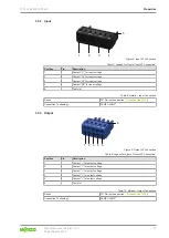
Page 15: ...5 Test slot Table 8 Details Input Connection Series 721 Series see section 8 Accessories 72 Connection Technology CAGE CLAMP 3 5 3 Output 1 2 3 4 5 6 Figure 5 Output X2 Connection Table 9 Legend for...

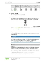
Page 16: ...icator This indicator consists of five LEDs These LEDs indicate operating states and Diagnostics 100 75 50 25 DC OK Figure 7 Optical Status Indicator Table 13 Indication of Operating States General In...

Page 17: ...to make settings 3 8 Communication interface The communication interface is covered with a cap Remove this cap to use the commu nication interface NOTICE Avoid destruction of the product by electrosta...

Page 18: ...to your PC 3 Carefully insert the plug for the communication interface straight into the communi cation interface in such a way that the keying tab fits into the lower recess The plug is seated correc...

Page 19: ...perty Value Mains failure buffering time typ 1 400 VAC 21 ms 480 VAC 43 ms Holding time typ 1 400 VAC 40 ms 480 VAC 40 ms 1 At nominal load Table 19 Technical Data Input Connection Property Value Cros...

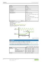
Page 20: ...50 VAC 3 10 90 load step 4 20 MHz bandwidth 5 See section 8 Short Circuit and Overload Behavior 64 6 Can be set via the WAGO Interface Configuration software 7 See figure Turn on Time Overshoot Turn o...

Page 21: ...ally insulated shaft type 2 see section 8 Accessories 72 3 9 4 Efficiency Power Loss Table 22 Technical Data Efficiency Power Loss Property Value Efficiency typ 1 400 VAC 92 8 480 VAC 92 0 Power loss...

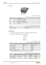
Page 22: ...toMOS Isolation voltage See section Safety Table 25 Technical Data Signal Connection Property Value Cross section Solid 0 08 2 5 mm 28 12 AWG Fine stranded 0 08 2 5 mm 28 12 AWG Insulated ferrule with...

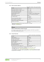
Page 23: ...g term storage For long term storage power must be applied to equipment with built in capacitors for five minutes at least every two years 3 9 9 Product Protection Table 29 Technical Data Product Prot...

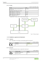
Page 24: ...olation voltage output digital input output digital output ref D 1 500 VAC 1 Type test rise 5 s stay 2 s fall 5 s see figure Dielectric Strength Input A D D D C B PE Digital Output Digital Input Outpu...

Page 25: ...tions EN 60870 2 2 3K3 except for low air pressure Table 34 Standards EMC Immunity to Interference Standard Title EN IEC 61204 3 Low Voltage Switch Mode Power Supplies Part 3 Electromagnetic Com patib...

Page 26: ...61000 4 2 Part 4 2 Testing and measurement techniques Electrostatic discharge immunity test Contact discharge 6 kV B Air discharge 2 kV 4 kV 8 kV B EN 61000 4 3 Part 4 3 Testing and measurement techn...

Page 27: ...disturbance measurements CISPR 16 2 1 Conducted distur bance AC input Class B residential area at nom inal load Conducted distur bance DC output Class B residential area at nom inal load EN 55016 2 3...

Page 28: ...344 0000 00x0 Properties 28 Product manual Version 1 0 1 Power Supply Pro 2 The manufacturer of the system or machine is responsible for ensuring compliance with the limit values required by EMC legis...

Page 29: ...connection via a WAGO USB Communication Cable see section Communication Interface or via a communication module that is available as an option The communication modules allow configuration and monitor...

Page 30: ...tection during transport and storage Store the product in suitable packaging preferably the original packaging Only transport the product in suitable containers packaging Make sure the product contact...

Page 31: ...djacent surfaces The letters shown in parentheses refer to positions in the View figure in section View Mounting Positions Nominal mounting position see also figure under View Front side facing forwar...

Page 32: ...15 by snapping it onto the DIN 35 rail see figure Mounting 1 Place the product with its DIN 35 rail guide on the top edge of the DIN 35 rail 2 Press the product onto the DIN 35 rail A while simultaneo...

Page 33: ...ve the maximum permissible conductor cross sections for the signal and power ca bles see section 8 Technical Data 18 Check the appropriate operating voltage before connecting the equipment see section...

Page 34: ...an up circuit wiring assembly for example using WAGO Through Terminal Blocks To connect the conductors use an operating tool see section Accessories or an appro priate screwdriver Perform the followin...

Page 35: ...Set output voltage Press once The output voltage increases in steps Press and hold The output voltage increases con tinuously Press once The output voltage is reduced in steps Press and hold The outp...

Page 36: ...d or Trip ping Current of Electronic Cir cuit Breaker Exceeded 100 Flashing 2 Hz Flashing 2 Hz Flashing 2 Hz 75 Off Flashing 2 Hz Signaling of regular utilization 50 Off Off 25 Off Off DC OK Flashing...

Page 37: ...ents Components Requirements Operating system Windows 10 64 bit Memory 8 GB Free hard disk space 250 MB Processor 1 GHz or higher 64 bit x64 Screen resolution 1920 1080 pixels 10 1 2 Install WAGO Inte...

Page 38: ...product to a computer via a WAGO USB Communication Cable 10 2 First Steps The following steps are based on the WAGO Interface Configuration software G2 Ver sion 01 00 06 18 and Firmware Version 01 05...

Page 39: ...Communication Selects the connection between the product and software Language Selects the display language for the software Help Opens the help for the software About Displays information about the s...

Page 40: ...anually selected or automatically detected by the software see the following steps The settings you have to make on this tab depend on whether you are configuring your product offline or online Offlin...

Page 41: ...for the Graphical User Interface Overview Pos Section Description 1 Menu Bar The menu bar contains general software settings options You can find more information in section Menu Bar 2 Main Menu The...

Page 42: ...meters and measured values which can be stored as a CSV file Simulation Opens the Simulation dialog The dialog is described in section 8 Dialog Simulation 52 Update Performs a firmware update on the p...

Page 43: ...gs Buttons Button Description Import Imports previously saved settings e g when a product is replaced or config uration is performed offline Export Saves the new settings externally The saved settings...

Page 44: ...this mode a smooth char acteristic curve ensures better current sharing for par allel operation of power supplies Enable switching the DC out put on and off via cyclic process data If this checkbox i...

Page 45: ...tronic Circuit Breaker overload behavior Latching after thermal over load If this checkbox is selected the Latching Shutdown on Thermal Overload overload behavior is enabled After an overtemperature e...

Page 46: ...ered by high low transition If this checkbox is selected the digital input is acti vated in the event of an edge change from 1 to 0 Digital output DC O K 1 If this checkbox is selected the digital out...

Page 47: ...arning thresholds Overload limit active If this checkbox is selected a warning is triggered if the overload warning threshold is exceeded Warning threshold Here you can enter the value for current uni...

Page 48: ...ins switched off 1 If this checkbox is selected the DC output remains switched off in the event of connection to the grid Switch on delay active If this checkbox is selected an additional switch on de...

Page 49: ...the con nected product with the system time of the PC Customer informa tion Location name Here you can enter additional information on the prod uct used All the input fields can be freely edited You...

Page 50: ...active If this checkbox is selected no parameters can be writ ten to the product Write and read protection ac tive If this checkbox is selected no parameters can be writ ten to the product or read fro...

Page 51: ...e information about the Modbus RTU Communication Module is available in the re spective Product Manual and in section 8 Accessories Communication 72 Figure 30 Dialog Settings Modbus Table 59 Dialog Se...

Page 52: ...ay of operating states warnings and errors All operating states warnings and errors can be displayed visually Identify the optimal setting options Optimal setting options for a specific load behavior...

Page 53: ...nabled in the Selection of the signal source operation panel Import load curve view This view appears if the Import load curve setting has been enabled in the Se lection of the signal source operation...

Page 54: ...ual points can thus be examined more closely Process Input Data Operation Panel Shows operating states warnings and errors General information on operating states warnings and errors is explained in t...

Page 55: ...o three measured values The representation in the Display section is described in section Display Sec tion Measurement Recording Last Error and Warning Mes sages Shows the last accumulated error messa...

Page 56: ...ements Section Indicator Description Output Voltage This indicates the current output voltage unit V Current This indicates the current output current unit A Power This indicates the current output po...

Page 57: ...emperature The displayed value is the sum over the previous operating time unit h The hours themselves are recorded and added up over the entire product life cycle Overheating device switched off This...

Page 58: ...splay Section Measurement Recording Pos Setting Description 1 Chart Clock Here you can specify whether a specific number of val ues chart or measured values over a specific time period clock should be...

Page 59: ...time Here you can enter the time when recording should start setting at pos 1 clock End time Here you can enter the time when recording should end setting at pos 1 clock Sample rate Here you can ente...

Page 60: ...ges Section Description No Consecutive number of the accumulated warning and error message Date Date of the accumulated warning and error message Time Time of the accumulated warning and error message...

Page 61: ...on the connect product Table 65 Display Section Information Indicator Description Order number This shows the order number of the product Description This shows the manufacturer s name for the product...

Page 62: ...t Side Overvoltage Protection 62 11 2 Disable Enable Overvoltage Protection The product is protected against overvoltage for more information see section 8 Over voltage Protection 29 The letters shown...

Page 63: ...o EN 62368 1 this sun must not exceed the maximum value of 3 5 mA 11 4 Derating The maximum load is a function of the surrounding air temperature and the installation al titude Table 66 Nominal values...

Page 64: ...in parallel Use external rail mount terminal blocks when connecting in parallel A parallel connection directly on the connectors on the secondary side of the product is not allowed For decoupling the...

Page 65: ...lasts longer a 15 second pause occurs during which the output voltage is switched off The output voltage is then switched back on If the overload is still present the process starts again This mode is...

Page 66: ...This process repeats until the overload has been eliminated t 100ms 500ms 150 100ms 100 IOUT IN Figure 41 Hiccup Mode 11 6 4 Electronic Circuit Breaker Mode In this mode a specified trip current and...

Page 67: ...witch the output back on manual intervention is necessary The following options are available for this Communication interface Buttons Digital input 11 6 6 Power Boost Mode This mode can be used in co...

Page 68: ...ndary circuit for example In some cases the current pulse can trip an overcurrent protection device that is present in the connected circuit such as a circuit breaker This quickly ends the short circu...

Page 69: ...at least every two years The product requires no special maintenance however it must be protected as per the protection class against dust accumulation moisture radiation and aggressive chemi cals Pe...

Page 70: ...osal benefits health protects the environ ment from harmful substances in electrical and electronic equipment and enables sus tainable and efficient use of resources Observe national and local regulat...

Page 71: ...illustrate examples of how a WAGO Power Supply Pro 2 can be connected as a consumer in three different grounding systems TN TT and IT 13 1 1 AC Operation Load Source AC 3 phase AC DC L1 L2 L3 PE Figur...

Page 72: ...er Supply Pro 2 Modbus TCP Communication Module 2789 9052 Attachable EtherNet IP Communication Mod ule for WAGO Power Supply Pro 2 EtherNet IP Communication Module 2789 9023 WAGO USB Communication Cab...

Page 73: ...ark of CODESYS Development GmbH DALI is a registered trademark of the Digital Illumination Interface Alliance DiiA EtherCAT is a registered trademark and patented technology licensed by Beckhoff Autom...

Page 74: ...18 Table 16 Technical Data AC Input 19 Table 17 Technical Data Inrush Current 19 Table 18 Technical Data Mains Failure Buffering Time 19 Table 19 Technical Data Input Connection 19 Table 20 Technical...

Page 75: ...Tabs 39 Table 50 Backstage Tab 39 Table 51 Device Tab 40 Table 52 Legend for the Graphical User Interface Overview 41 Table 53 Device Tab 42 Table 54 Dialog Settings Buttons 43 Table 55 Dialog Setting...

Page 76: ...Removing 32 Figure 17 Connect Conductor to CAGE CLAMP 34 Figure 18 Software Start 38 Figure 19 Start View 38 Figure 20 Start View Tabs 38 Figure 21 Backstage Tab 39 Figure 22 Device Tab Selection Menu...

Page 77: ...dent 64 Figure 39 Constant Current Mode 65 Figure 40 Constant Current with Latching Shutdown Mode 66 Figure 41 Hiccup Mode 66 Figure 42 Electronic Circuit Breaker Mode 67 Figure 43 Power Boost Mode in...

Page 78: ...gs videos and other WAGO media are subject to copyright Distri bution or modification of the contents of these pages and videos is prohibited Furthermore the content may neither be copied nor made ava...

Reviews: