
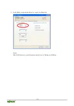
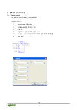


11
5
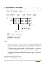
Relation between objects and I/O module
The relation between objects and I/O modules is as follows. Please refer to the Modular I/O System
CANopen 750-337 Manual for the details. The values in parentheses are ones in the manufacturer area; for
example, 0x6000 and 0x2000 are the same value.
0x6000
Digital input
(0x2000)
0x6200
Digital output
(0x2100)
0x6401
Analog input
(0x2400)
0x6411
Analog output
(0x2500)
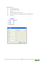
e.g.)
* Object
Data areas of objects are identified as follows.
Commutation area
0x1000 to 0x1FFFF
Manufacturer area
0x2000 to 0x5FFF
Profile area
0x6000 to 0x9FFF
* NOTE
-
As for the transmission of analog input data, CAN messages can be sent even when tiny variations of
values are found. This may cause an overflow. To avoid this, the transmission of analog input data via
PDOs is deactivated by default. This communication load can be inhibited by the “inhibit time” of the
slave settings. Please refer to 5.2.1 Parameters (POD settings) for the details. For the transmission of
analog input/output data using the object 0x6401 or 0x6411, set the object 0x6423, Analog Input
Global Interrupt Enable, which is to control the transmission of analog input data using PDOs, to 1.
-
For the transmission of analog input/output data using the object 0x2400 or 0x2500, the above setting is
not necessary. The objects 0x2000s to 0x5000s are in the manufacture area and they do not depend on
the above setting.
-
Index 0x6423:Analog Input Global Interrupt Enable
Sub Index0: = [ 1 ] The default value is set to “0”.
WAGO
750-337
8-CH
Digital
Input
2-CH
Analog
Input
2-CH
Analog
Output
8-CH
Digital
Output
2-CH
Analog
Input
0x6401.03
0x6200.01
0x6411.01, 0x6411.02
0x6401.01, 0x6401.02
0x6000.01, 0x6000.02
Summary of Contents for 750-337
Page 4: ......


