74
Function Description
WAGO-I/O-System 750
750-370 PROFINET IO Fieldbus Coupler
Manual
Version 2.0.0
Pos: 66.3 /Serie 750 (WAGO-I/O-SYST EM)/F unktionsbeschr eibung/Funkti onsbeschrei bung Stationshochl auf- und Initi alisierung 750-370,-375, - 377 - T eil 1.1 @ 15\mod_1370510165464_21.docx @ 122000 @ 2 @ 1
7.1
Device Start-Up and Initialization
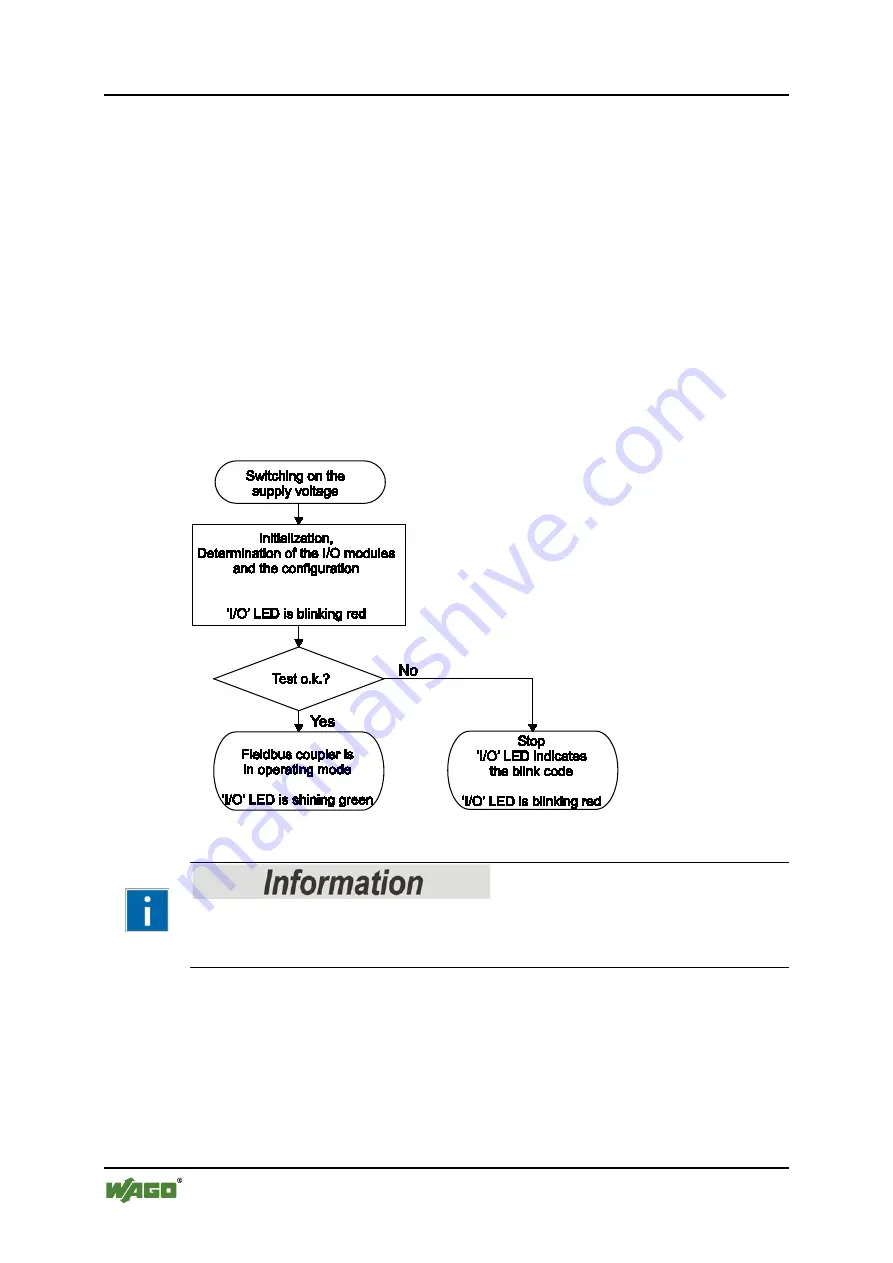
After a restart the fieldbus coupler does several hardware tests, e.g. the check of
memory components.
Successfully passed those tests it initializes the internal communication system K-
Bus to identify the arranged I/O modules and to exchange information with them.
This phase is indicated by the I/O LED, which flashes red at 10 Hz. Subsequent to
the successful K-Bus initialization the I/O-LED changes to green on-state.
The fieldbus coupler then switches to the “Fieldbus Start” state in which it waits
for the connection with the higher-level control system (IO controller) as an IO
device.
If an error occurs during start-up, the I/O LED flashes red and a blink code
indicates the respective error message.
Pos: 66.4.1 /Serie 750 (WAGO-I/O-SYST EM)/F unktionsbeschr eibung/Betriebssystem/Initialisi erung (Betriebssystem Koppl er) - PR OFIN ET @ 13\mod_1353928290758_21.docx @ 106950 @ @ 1
Figure 37: Fieldbus Coupler Operating System
Pos: 66.4.2 /Serie 750 (WAGO-I/O-SYST EM)/Gerätebeschrei bung/Anzeigeelemente/Fel dbuskoppl er/-contr oller/Leg ende/Infor mation: Infor mationen zu der LED- Signalisi erung @ 4\mod_1239098329547_21.docx @ 30154 @ @ 1
More information about the LED Signaling
Read the detailed description for the evaluation of the displayed LED state in the
section “Diagnostics” > … > “LED Signaling”.
Pos: 66.5 /Dokumentation allgemei n/Glieder ungselemente/---Seitenwechsel--- @ 3\mod_1221108045078_0.docx @ 21810 @ @ 1


