WAGO-I/O-SYSTEM 750
Device Description
45
750-375 PROFINET IO advanced Fieldbus Coupler
Manual
Version 1.1.0
Pos : 24 /All e Seri en (Allgemei ne Module)/Ü berschrif ten f ür alle Serien/G erätebesc hreibung/Ansic ht - Ü berschrif t 2 @ 4\ mod_1240984217343_21. doc x @ 31958 @ 2 @ 1
4.2
View
Pos : 25.1 /Serie 750 (WAGO-I/ O-SYST EM)/ Ger ätebesc hrei bung/Ansic ht /Fel dbus koppl er/-contr oller/ Leg ende/Ansic ht - allg. Einl eit ung f ür PROF INET IRT-Koppl er (750-375) @ 13\ mod_1353429523679_21. doc x @ 106590 @ @ 1
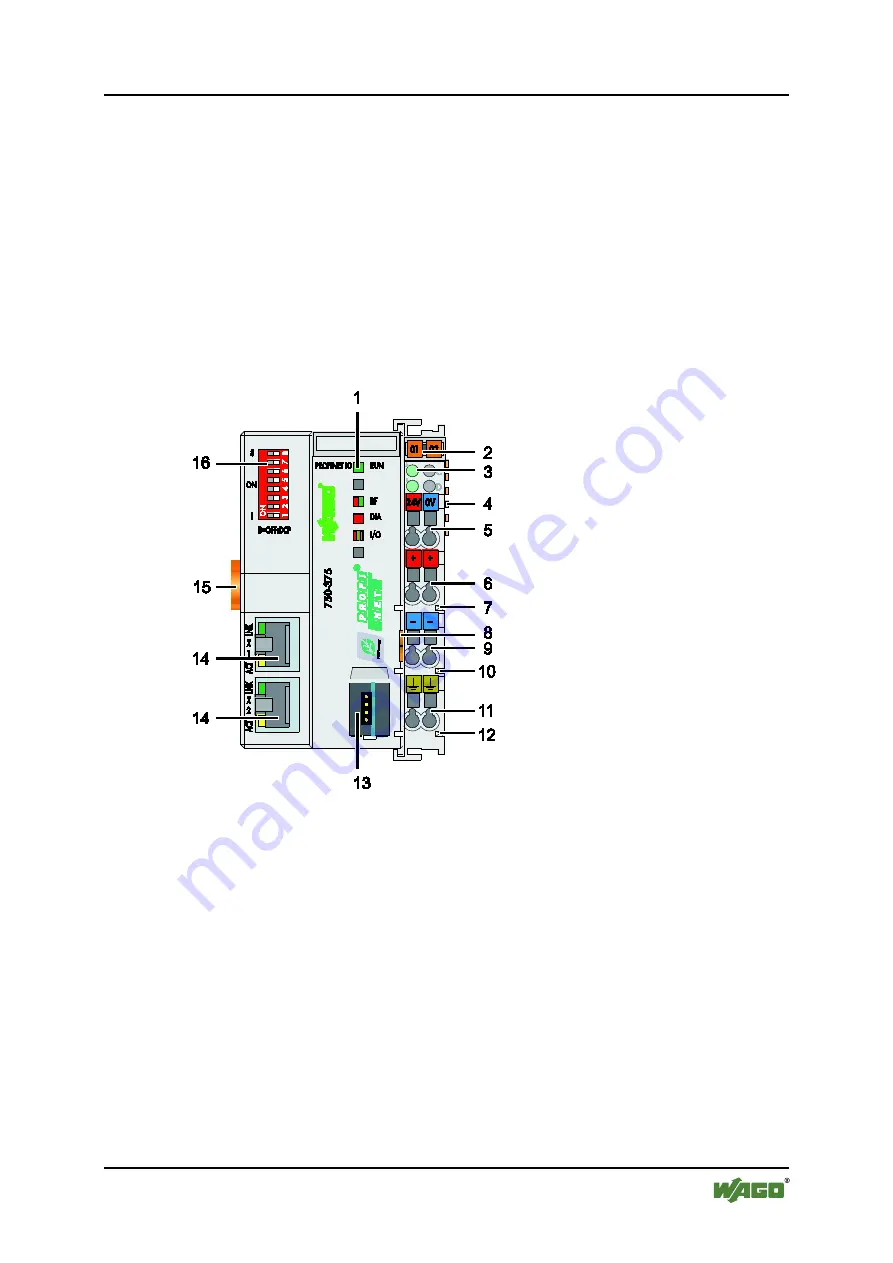
The view shows three different units of the device:
•
There is a DIP switch at the top left and below that the fieldbus connection
(X1, X2).
•
LEDs for operation status, bus communication, error messages and
diagnostics, as well as the service interface behind the flap are in the middle
area.
•
The right side shows a power supply unit for the system supply and for the
field power of the attached I/O modules via power jumper contacts.
LEDs show the status of the operating voltage for the system and field
power (jumper contacts).
Pos : 25.2 /Serie 750 (WAGO-I/ O-SYST EM)/ Ger ätebesc hrei bung/Ansic ht /Fel dbus koppl er/-contr oller/ Bilder/Ansic ht - Bild 750-0375 @ 13\ mod_1353330469183_21. doc x @ 106440 @ @ 1
Firgure 21: View Fieldbus coupler PROFINET IO advanced
Pos : 25.3 /Dokumentation allgemei n/ Glieder ungs elemente/---Seit enwechs el--- @ 3\ mod_1221108045078_0.doc x @ 21810 @ @ 1


