66
Mounting
WAGO-I/O-SYSTEM 750
750-375 PROFINET IO advanced Fieldbus Coupler
Manual
Version 1.1.0
Pos : 57.15 / Serie 750 ( WAG O-I/ O-SYST EM)/Monti eren/D emonti eren/F eldbus koppler/-c ontroll er ei nf ügen @ 3\ mod_1234168173031_21. doc x @ 27456 @ 3 @ 1
5.6.1
Inserting the Fieldbus Coupler/Controller
1.
When replacing the fieldbus coupler/controller for an already available
fieldbus coupler/controller, position the new fieldbus coupler/controller so
that the tongue and groove joints to the subsequent I/O module are engaged.
2.
Snap the fieldbus coupler/controller onto the carrier rail.
3.
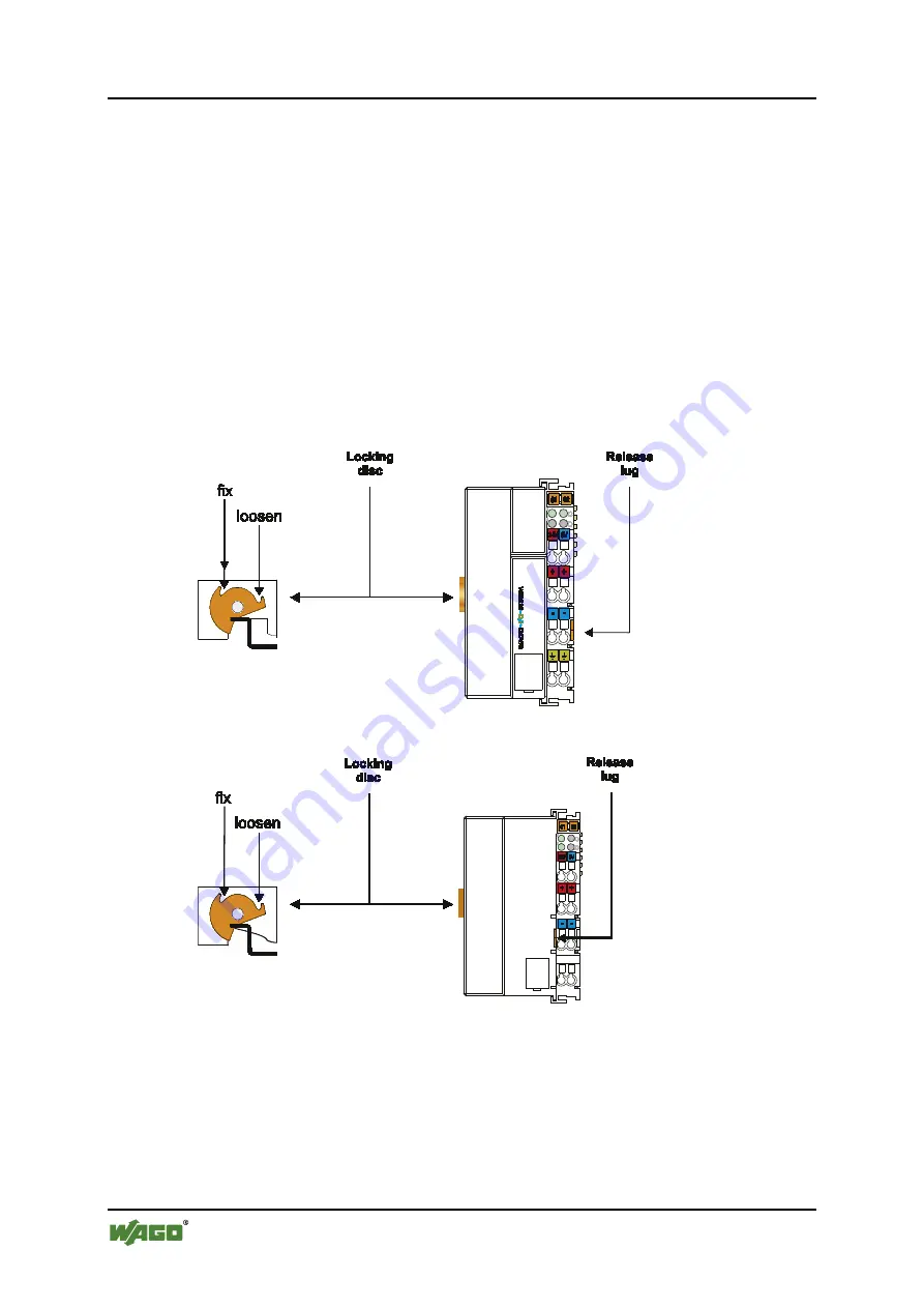
Use a screwdriver blade to turn the locking disc until the nose of the locking
disc engages behind the carrier rail (see the following figure). This prevents
the fieldbus coupler/controller from canting on the carrier rail.
With the fieldbus coupler/controller snapped in place, the electrical connections
for the data contacts and power contacts (if any) to the possible subsequent I/O
module are established.
Pos : 57.16 / Serie 750 ( WAG O-I/ O-SYST EM)/Monti eren/D emonti eren/ Verrieg elung - Bil d (Standar d) @ 3\ mod_1231768944875_21.doc x @ 25953 @ @ 1
Figure 29: Unlocking lug standard fieldbus coupler/controller (example)
Pos : 57.17 / Serie 750 ( WAG O-I/ O-SYST EM)/Monti eren/D emonti eren/ Verrieg elung - Bil d (er weit erter ECO) @ 3\ mod_1231769519703_21.doc x @ 25979 @ @ 1
Figure 30: Unlocking lug of extended ECO fieldbus coupler (example)
Pos : 57.18 / Serie 750 ( WAG O-I/ O-SYST EM)/Monti eren/D emonti eren/ Verrieg elung - Bil d (EC O) @ 3\ mod_1231769448312_21. doc x @ 25975 @ @ 1


