36 Process Image
WAGO I/O SYSTEM 750 XTR
750-633/040-000 Up/Down Counter Ex i XTR
Manual
Version 1.1.0
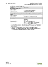
Table 26: Status Byte S0, Operating Modes 1 and 2
Bit 7
Bit 6
Bit 5
Bit 4
Bit 3
Bit 2
Bit 1
Bit 0
X
NAMUR_
ERR
CNT_SET CNT_INH
X
ST_DO
ST_U/D
(GATE)
ST_CLK
ST_CLK
Status input CLOCK
ST_U/D(GATE) Status input U/D (Gate)
ST_DO
Status output DO
CNT_INH
Feedback message counter locked
CNT_SET
Counter feedback message set
NAMUR_ERR
Namur error at input
*)
X
This value is not defined and cannot be evaluated.
*)
In the error state (bit 6 is set), the status bits 0, 1, 2, 3, 4, 5 are always set to 0.
The following functions can be executed:
4.1.1
Set Counter
If bit 5 is set in the control byte, the counter is loaded with the 32-bit value from
output bytes 0 to 3. As long as the bit is set, the counter is stopped and the load
value stays the same. Bit 5 in the status byte indicates when the counter is
successfully loaded.
4.1.2
Disable Counter
If bit 4 is set in the control byte, counts are locked. Bit 4 in the status byte shows
when the counter is locked.
4.1.3
Set Output
Bit 2 of the control byte sets the digital output DO.
4.1.4
Example
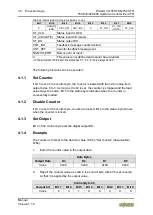
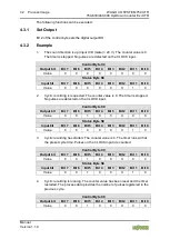
The counter is first set to the decimal value 100 by “Set counter” (hexadecimal
0x64):
1.
Enter the counter value in the output data.
Data Bytes
Output Data
D3
D2
D1
D0
Value
0x00
0x00
0x00
0x64
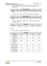
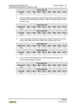
2.
Report the counter value as valid in the control byte with bit 5 (set counter),
so that it is applied as the output value.
Control Byte C0
Output bit
Bit 7 Bit 6 Bit 5 Bit 4 Bit 3 Bit 2 Bit 1 Bit 0
Value
0
X
1
X
X
X
X
X


