42 Process Image
WAGO I/O SYSTEM 750 XTR
750-633/040-000 Up/Down Counter Ex i XTR
Manual
Version 1.1.0
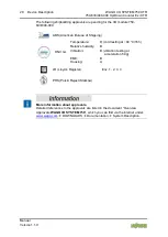
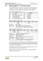
The following functions can be executed:
4.3.1
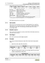
Set Output
Bit 2 of the control byte sets the digital output DO.
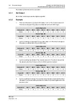
4.3.2
Example
1.
The count direction is up (input U/D (Gate) = 24 V). The counter value is 0.
The timer is stopped. No pulses are detected on the CLOCK input.
Control Byte C0
Output bit
Bit 7 Bit 6 Bit 5 Bit 4 Bit 3 Bit 2 Bit 1 Bit 0
Value
0
0
0
0
0
X
0
0
Status Byte S0
Input bit
Bit 7 Bit 6 Bit 5 Bit 4 Bit 3 Bit 2 Bit 1 Bit 0
Value
0
0
0
0
0
X
1
0
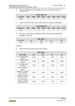
2.
Cyclic recording is requested. The counter value is 0. The timer is stopped.
No pulses are detected on the CLOCK input.
Control Byte C0
Output bit
Bit 7 Bit 6 Bit 5 Bit 4 Bit 3 Bit 2 Bit 1 Bit 0
Value
0
0
1
0
0
X
0
0
Status Byte S0
Input bit
Bit 7 Bit 6 Bit 5 Bit 4 Bit 3 Bit 2 Bit 1 Bit 0
Value
0
0
0
0
0
X
1
0
3.
Cyclic recording has started. The counter value is 0. The timer runs with at
the preset cycle time. Pulses on the CLOCK input are counted.
Control Byte C0
Output bit
Bit 7 Bit 6 Bit 5 Bit 4 Bit 3 Bit 2 Bit 1 Bit 0
Value
0
0
1
0
0
X
0
0
Status Byte S0
Input bit
Bit 7 Bit 6 Bit 5 Bit 4 Bit 3 Bit 2 Bit 1 Bit 0
Value
0
0
1
0
0
X
1
0
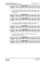
4.
Cyclic recording is running. The counter value has been reset and the timer
restarted. The process data provides the number of pulses registered in the
previous cycle.
Control Byte C0
Output bit
Bit 7 Bit 6 Bit 5 Bit 4 Bit 3 Bit 2 Bit 1 Bit 0
Value
0
0
1
0
0
X
0
0

