58 Parameterizing
WAGO I/O SYSTEM 750 XTR
750-633/040-000 Up/Down Counter Ex i XTR
Manual
Version 1.1.0
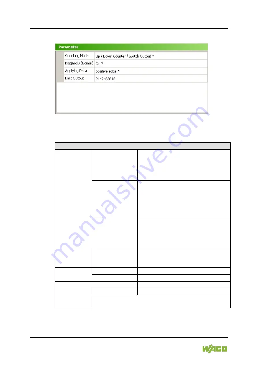
7.1.1.2 Parameter
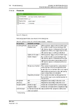
Figure 18: Parameter
Following select boxes are shown in the dialog box:
Table 40: Up/Down Counter Ex i XTR (750-633/040-000) – Parameter
Select box
Available settings
Counting Mode Up Counter with
Enable Input
With a positive edge on the CLOCK input,
the counter counts up (ascending) if the
U/D (Gate) input is connected with a high
signal level. With a low signal level on the
U/D (Gate) input, counting is disabled.
Up/Down Counter /
Switch Output
*)
With a positive edge on the CLOCK input,
the counter counts up (ascending) if the
U/D (Gate) input is connected with a high
signal level and down (descending) if the
U/D (Gate) input is connected with a low
signal level.
Frequency Counter The counter measures the cycle duration
of the signal on the CLK input if the U/D
(Gate) input is connected with a low signal.
With a high signal level on the U/D (Gate)
input, measurement is disabled.
Peak-time Counter The counter records counting pulses on
the CLOCK input over a defined period of
10 seconds.
Diagnosis
(Namur)
Off
Diagnostics according to Namur is off.
On
*)
Diagnostics according to Namur is on.
Applying Data positive edge
*)
Values are accepted with a positive edge.
negative edge
Values are accepted with a negative edge.
Limit Output
In this field, enter the value at which the output is switched on
when exceeded.
*)
Default setting

