WAGO I/O System 750
Device Description 17
750-637 Incremental Encoder Interfaces
Manual
Version 1.6.1
Public
Starting with the software version XXXX03XX, the cam outputs can be disabled
by the control unit and the states of the cam outputs can be queried.
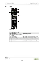
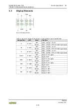
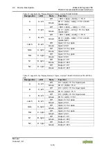
The signal status for inputs A, B and C, Latch and Gate and the operating status
of the I/O module are each indicated by a dedicated green status LED.
The meaning of the LEDs is described in the “Display Elements” section.
Power supply for 24 V encoders is provided via the 24 V field supply connections.
The encoder ground must be connected with the 0 V module.
Power supply for 5 V encoders can be tapped directly at connections V
e
and V
0
of
the standard module 750-637.
Use a power supply module!
Use a power supply module for field-side power supply of downstream I/O
modules.
The field voltage and the system voltage are electrically isolated from each other.
The I/O module 750-637 can be used with all fieldbus couplers/controllers of the
WAGO I/O System 750 (except for the economy types 750-320, -323, -324
and -327).


