WAGO-I/O-SYSTEM 750 XTR
Commissioning 63
750-652/040-000 Serial Interface RS-232/RS-485 XTR
Manual
Version 1.3.0
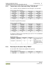
Table 44: Transmission of a Block of 1 to 512 Bytes
Control byte 0
Control byte 1
'0110.1001'
'0XXX. X101'
Controller fills the output buffer with 46 bytes and set bit 3
(SC) of the control byte 0 for the start of the transmission.
Status byte 0
Status byte 1
'0XXX.X0X1'
'0000. 1XXX'
I/O module confirms the acceptance of the data.
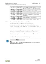
Control byte 0
Control byte 1
'0110.1000'
'0XXX. X101'
Controller takes bit 0 (TR) of the control byte 0 back.
Status byte 0
Status byte 1
'0XXX.X0X0'
'0XXX. 0XXX'
I/O module begins with the data transmission via the
serial interface.
Status byte 0
Status byte 1
'0XXX.X0X1'
'0000. 1XXX'
All data is transmitted via the serial interface.
Control byte 0
Control byte 1
'0XXX.0XX0'
'0XXX. 1XXX'
Controller takes bit 3 (TR) of the control byte 0 back.
8.3.5.2 Transmission of a Block of More than 512 Bytes
The output buffer is filled up with data up to number 512 bytes.
To transmit the buffer content, the bit 3 (SC) of the control byte 0 is set by the
controller. The I/O module begins with the data transmission and the bit 3 (BUF_E)
of the status byte 1 is reset.
During transmission, the output buffer continues to be filled up by the controller.
Bit 3 (SC) of control byte 0 is set by the controller as long as data should be
transmitted. The I/O module acknowledges data transmission by resetting bit 3
(BUF_E) in status byte 1.
Then bit 3 (SC) of control byte 0 is taken back by the controller. The end of the
transmission from the I/O module is detected this way.
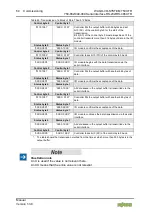
NOTE
At higher baud rates, it cannot be ensured that more than 512 bytes of data are
transmitted as a contiguous block!


