14 • Example “Mapped mode”
Application note
A500680e
5 Example “Mapped mode”
5.1 Configuration of module size
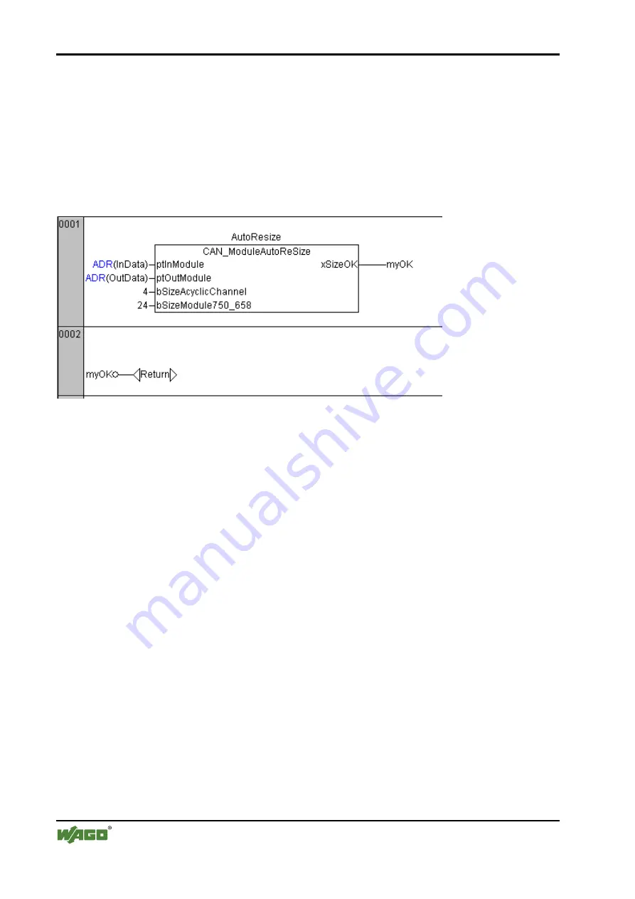
The example project includes in the first network a function block, which checks the
CAN_gateway module size by power up.
This block must be the first block in an application program. This block will reset the controller
in case that the module size needs to be adjusted. Therefore this block will only work, if the li-
brary WagoLibReset is supported by the target system.
5.2 Configuration of filter and mapping data by CoDeSys
It is assumed that the node ID of the CANopen slave is 4. The slave will transmit one PDO
(0x184) with two bytes data. This data is received in inData[8] and inData[9] .
The slave will receive one PDO (0x204) with one byte data. Byte counting within PDOs starts
with 0 (D0, D1..D7). The transmitted data must be placed in OutData[8] .
Before the data exchange will start, the configuration of the gateway module is checked. If the
module settings do not match with the settings in the application program, the module will be
reconfigured. This technic allows replacing a faulty module without additional tooling.
The configuration will be explained in detail, though it is recommended to do the first configura-
tion with Wago-IO-Check and take over manually the configuration to the CoDeSys structure
CAN_typFullConfiguration.
The configuration is subdivided in four sections. The register area is set in Register 32 according
to 16#8230. This is 11bit mode, 125kBaude, mapped mode with active SDO communication us-
ing the acyclic channel.
The setting of these registers should not be changed unless a different configuration is used.
Please check the manual for detailed explanation of the bits within the registers.


