36 Process Image
WAGO-I/O-SYSTEM 750
750-658 CAN Gateway
Manual
Version 1.2.1, valid from FW/HW-Version 01/01
6
Process Image
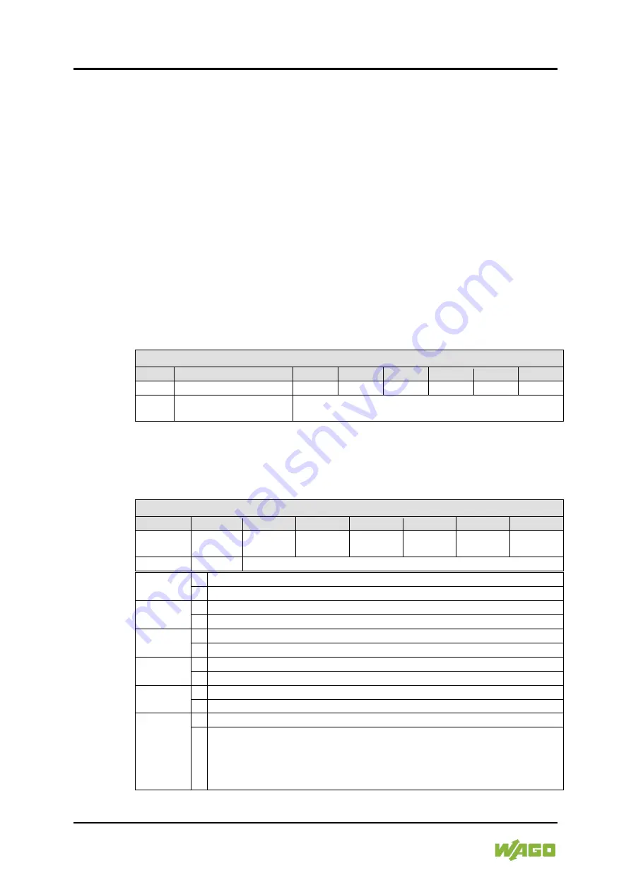
The first byte of the local bus process image is:
•
The
control byte
in the process output direction
•
The
status byte
in the process input direction
The mailbox is static in the process image and is cross-faded when register
communication is on.
During register communication, the register query response is contained in the
status byte followed by 2 bytes of register data.
If the mailbox is active, status information of the I/O module is displayed cyclically
via the status byte.
Control byte
Table 17: Control Byte
Control Byte
Bit 7
Bit 6
Bit 5
Bit 4
Bit 3
Bit 2
Bit 1
Bit 0
0
res.*
res.*
res.*
res.*
res.*
res.*
res.*
1
0 = Read register
1 = Write register
Register number
* Reserved
Status byte
Table 18: Status Byte
Status Byte
Bit 7
Bit 6
Bit 5
Bit 4
Bit 3
Bit 2
Bit 1
Bit 0
0
GEN_
ERR
CAN_
ERR
TX_
OVF
RX_
OVF
INT_
ERR
1
Res.
Register number
(Bit 7)
0 Mailbox 0 active
1 Register communication enabled
GEN_ERR 0 No error on the CAN Bus.
1 Error on the CAN bus. Set when one of the bits 0…5 = 1.
CAN_ERR 0 No error on the CAN Bus.
1 Error on the CAN bus.
TX_OVF
0 Send buffer OK.
1 Send buffer overflow (downstream). No data can be received by the I/O module.
RX_OVF
0 Receive buffer OK.
1 Receive buffer overflow (upstream). No data can be received by the I/O module.
INT_ERR 0 No internal error.
1 Internal error. Possible causes:
• 24V field supply missing
• Communication via mailbox and process data faulty
• Faulty parameterization request
• Faulty register request


