WAGO-I/O-SYSTEM 750
Assembly
69
750-880, 750-880/025-000 ETHERNET Programmable Fieldbus Controller
Manual
Version 1.0.1
Pos: 61.17 /Serie 750 (WAGO-I/O-SYSTEM)/Montieren/Feldbuskoppler/-controller einfügen @ 3\mod_1234168173031_21.doc @ 27456 @ 3 @ 1
5.6.1
Inserting the Fieldbus Coupler/Controller
1.
When replacing the fieldbus coupler/controller for an already available
fieldbus coupler/controller, position the new fieldbus coupler/controller so
that the tongue and groove joints to the subsequent I/O module are engaged.
2.
Snap the fieldbus coupler/controller onto the carrier rail.
3.
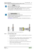
Use a screwdriver blade to turn the locking disc until the nose of the locking
disc engages behind the carrier rail (see the following figure). This prevents
the fieldbus coupler/controller from canting on the carrier rail.
With the fieldbus coupler/controller snapped in place, the electrical connections
for the data contacts and power contacts (if any) to the possible subsequent I/O
module are established.
Pos: 61.18 /Serie 750 (WAGO-I/O-SYSTEM)/Montieren/Verriegelung - Bild (erweiterter ECO) @ 3\mod_1231769519703_21.doc @ 25979 @ @ 1
24
V 0V
+ +
- -
PE PE
0
1
0
2
C
D
B
A
f
i
x
l
oosen
Re
l
ease
l
u
g
L
o
c
king
d
i
sc
Figure 30: Unlocking lug of extended ECO coupler
Pos: 61.19 /Serie 750 (WAGO-I/O-SYSTEM)/Montieren/Feldbuskoppler/-controller entfernen @ 4\mod_1239169358453_21.doc @ 30330 @ 3 @ 1
5.6.2
Removing the Fieldbus Coupler/Controller
1.
Use a screwdriver blade to turn the locking disc until the nose of the locking
disc no longer engages behind the carrier rail.
2.
Remove the fieldbus coupler/controller from the assembly by pulling the
release tab.
Electrical connections for data or power contacts to adjacent I/O modules are
disconnected when removing the fieldbus coupler/controller.
Pos: 61.20 /Dokumentation allgemein/Gliederungselemente/---Seitenwechsel--- @ 3\mod_1221108045078_0.doc @ 21810 @ @ 1

