WAGO-I/O-SYSTEM 750
Device Description
49
750-880, 750-880/025-000 ETHERNET Programmable Fieldbus Controller
Manual
Version 1.0.1
Pos: 31 /Alle Serien (Allgemeine Module)/Überschriften für alle Serien/Anzeigeelemente - Überschrift 2 @ 4\mod_1240984390875_21.doc @ 31964 @ 2 @ 1
4.3
Display Elements
Pos: 32.1 /Serie 750 (WAGO-I/O-SYSTEM)/Gerätebeschreibung/Anzeigeelemente/Feldbuskoppler/-controller/Legende/Anzeigeelemente - Einleitung (Controller) @ 4\mod_1241005850082_21.doc @ 32020 @ @ 1
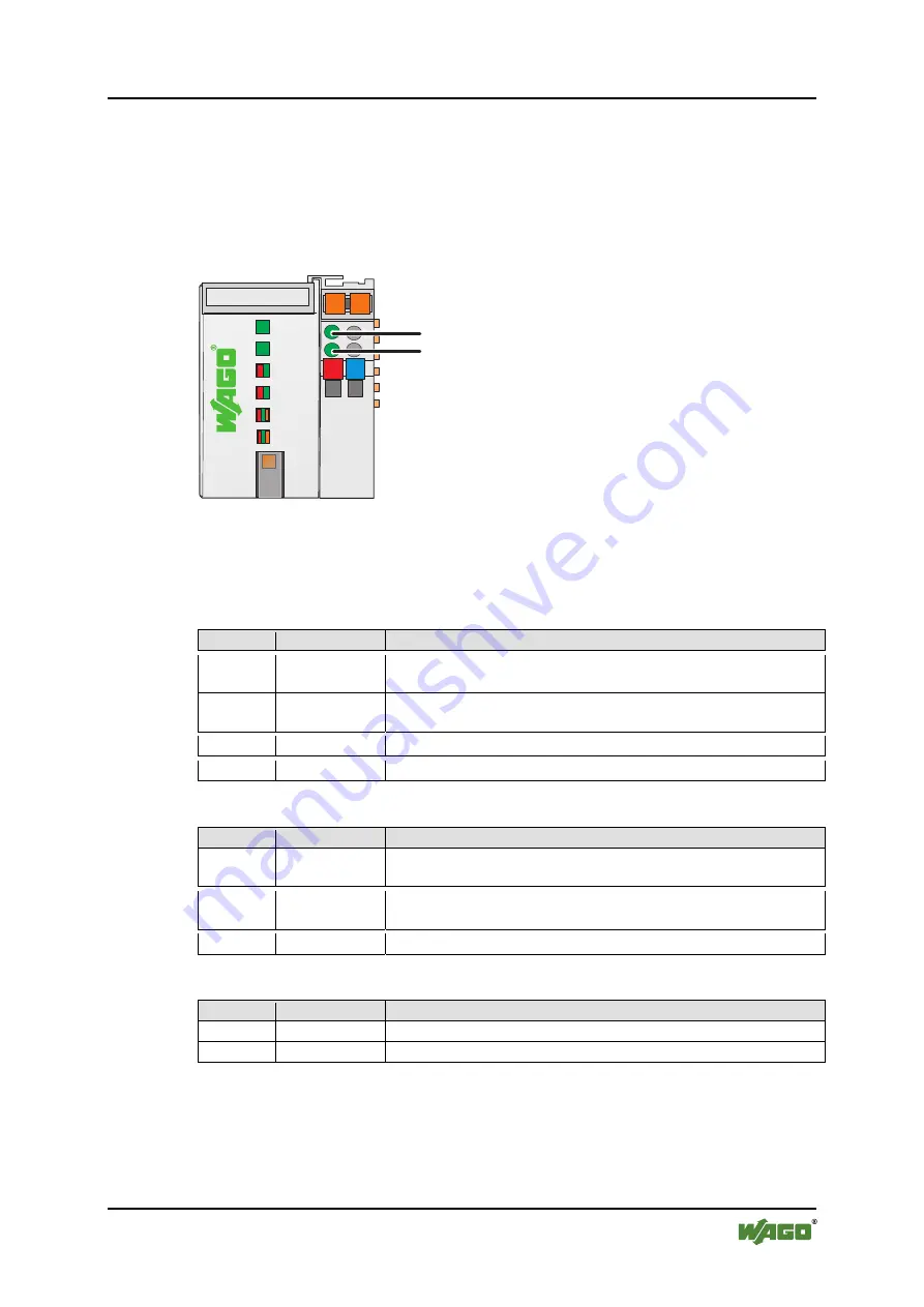
The operating condition of the controller or the node is displayed with the help of
illuminated indicators in the form of light-emitting diodes (LEDs).
The LED information is routed to the top of the case by light fibres. In some
cases, these are multi-colored (red, green or red/green (=orange)).
Pos: 32.2 /Serie 750 (WAGO-I/O-SYSTEM)/Gerätebeschreibung/Anzeigeelemente/Feldbuskoppler/-controller/Bilder/Anzeigeelemente 750-0880 - Bild @ 9\mod_1289492519593_0.doc @ 66387 @ @ 1
LINK
ACT
MS
I/O
ETHERNET
NS
LINK
ACT 1
2
USR
2
4
V 0V
01
02
C
D
B
A
A
B
SD
Figure 24: Display Elements
Pos: 32.3 /Serie 750 (WAGO-I/O-SYSTEM)/Gerätebeschreibung/Anzeigeelemente/Feldbuskoppler/-controller/Legende/Anzeigeelemente - Einleitung und Tabellenüberschrift Feldbusstatus (Standard) @ 4\mod_1240920871636_21.doc @ 31795 @ @ 1
+
For the diagnostics of the different ranges fieldbus, node and supply voltage, the
LED’s can be divided into three groups:
Table 11: Display Elements Fieldbus Status
LED
Color
Meaning
Pos: 32.4 /Serie 750 (WAGO-I/O-SYSTEM)/Gerätebeschreibung/Anzeigeelemente/Feldbuskoppler/-controller/Legende/Anzeigeelemente - Feldbusstatus ETHERNET-basiert, spezifischer Tabellenteil 'LINK ACT1,2' @ 5\mod_1253106696993_21.doc @ 41692 @ @ 1
LINK
ACT 1
green
indicates a connection to the physical network at port 1
LINK
ACT 2
green
indicates a connection to the physical network at port 2
Pos: 32.5 /Serie 750 (WAGO-I/O-SYSTEM)/Gerätebeschreibung/Anzeigeelemente/Feldbuskoppler/-controller/Legende/Anzeigeelemente - Feldbusstatus ETHERNET-basiert, spezifischer Tabellenteil 'MS' @ 5\mod_1253105531004_21.doc @ 41680 @ @ 1
MS
red/green
indicates the status of the node
Pos: 32.6 /Serie 750 (WAGO-I/O-SYSTEM)/Gerätebeschreibung/Anzeigeelemente/Feldbuskoppler/-controller/Legende/Anzeigeelemente - Feldbusstatus ETHERNET-basiert, spezifischer Tabellenteil 'NS' @ 4\mod_1240920458789_21.doc @ 31743 @ @ 1
NS
red/green
indicates the network status
Pos: 32.7 /Serie 750 (WAGO-I/O-SYSTEM)/Gerätebeschreibung/Anzeigeelemente/Feldbuskoppler/-controller/Legende/Anzeigeelemente - Knotenstatus Tabellenüberschrift und 'I/O' @ 4\mod_1240921390924_21.doc @ 31809 @ @ 1
+
Table 12: Display Elements Node Status
LED
Color
Meaning
I/O red/green/
orange
indicates the operation of the node and signals via a blink code faults
encountered
Pos: 32.8 /Serie 750 (WAGO-I/O-SYSTEM)/Gerätebeschreibung/Anzeigeelemente/Feldbuskoppler/-controller/Legende/Anzeigeelemente - Knotenstatus 'USR' (Controller) @ 4\mod_1240921467136_21.doc @ 31813 @ @ 1
USR red/green/
orange
indicates information to the Internal bus faults, controlled from the
user programm according to the visualization programming.
Pos: 32.9 /Serie 750 (WAGO-I/O-SYSTEM)/Gerätebeschreibung/Anzeigeelemente/Feldbuskoppler/-controller/Legende/Anzeigeelemente - Speicherkartenstatus 'SD' (750-0880) @ 9\mod_1291715745543_21.doc @ 67173 @ @ 1
SD
orange
indicates an access to the SD memory card
Pos: 32.10 /Serie 750 (WAGO-I/O-SYSTEM)/Gerätebeschreibung/Anzeigeelemente/Feldbuskoppler/-controller/Legende/Anzeigeelemente - Versorgungsspannungsstatus Tabellenüberschrift und 'A', 'B' @ 5\mod_1253265337073_21.doc @ 41846 @ @ 1
+
Table 13: Display Elements Supply Voltage
LED
Color
Meaning
A
green
indicates the status of the operating voltage – system
B
green
indicates the status of the operating voltage – power jumper contacts
Pos: 32.11 /Serie 750 (WAGO-I/O-SYSTEM)/Gerätebeschreibung/Anzeigeelemente/Feldbuskoppler/-controller/Legende/Information: Informationen zu der LED-Signalisierung @ 4\mod_1239098329547_21.doc @ 30154 @ @ 1


