16
Device Description
WAGO-I/O-SYSTEM 758
758-915
Bluetooth
®
ETHERNET Gateway
Manual
Version 1.1.0, applicable from FW/HW Version 01/01
3.3
Connectors
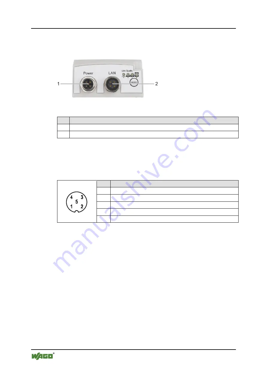
The device is equipped with two connections at the bottom:
Figure 6: Connections at bottom of device
Table 5: Legend for the “Connections at bottom of device” figure
No. Description
1
Power supply and trigger input (“Power”)
2
Network connection (“LAN”)
3.3.1
Pin Assignment for Power Supply
Power is supplied to the device via a 5-pole, A-coded M12 connector.
Table 6: Power supply, M12 Connector on Device
Pin Pin assignment
1 V
in
+ (9 V … 30 VDC)
2 Trigger input ground
3 V
in
Ground (0 V)
4 Trigger-input + (9 V … 30 VDC)
5 Not in use
The trigger input reacts to rising flanks and can be used for setting up and
terminating radio links (see Section “Configuration using the Mode membrane
button” / “Configuration via the Web-based Management System (WBM)”).
3.3.2
Pin Assignment for System Connection
The device is connected to the ETHERNET network via a 4-pole, D-coded socket
and supports autonegotiation for 10/100 Mbit and the duplex mode.


