background image

WAGO-I/O-SYSTEM 758 

Appendix 

63 

758-916 WLAN ETHERNET Gateway 2.4 GHz 


Manual 


Version 1.0.1, applicable from HW/SW Version 01/01 


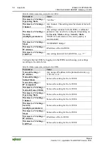
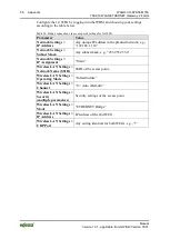
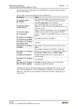
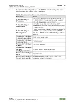
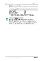
To implement this configuration, use the WBM to enter the settings described 

below for each WEG used as a wireless adapter. 

Table 31: Direct connection, with access point, configuration 

Parameter 

Value 

Network Settings > 

IP Address 

Any unique IP address in the planned network, e.g., 

“192.168.1.110”. This parameter is only required 

when 

IP Assignment

 is set to “Static”. 

Network Settings > 

Subnet Mask 

Any subnet mask that covers the range of IP 

addresses of all devices in the planned network, e.g., 

“255.255.255.0”. 

Network Settings > 

IP Assignment 

“Static” when the IP address is to be set manually. If 

a DHCP server is active in the network, “DHCP 

Client” or “DHCP Client & DHCP Relay” can be set 

instead. 

Wireless LAN Settings > 

Network Name (SSID) 

SSID of the access point 

Wireless LAN Settings > 

Operating Mode 

“Infrastructure” 

Wireless LAN Settings > 

Channel 

“0 = Auto (Default)” 

Wireless LAN Settings > 

Security 

(multiple parameters) 

Security settings of the access point 

Wireless LAN Settings > 

Mode 

“Client Mode” 

Wireless LAN Settings > 

WLAN MAC Address 

ETHERNET MAC address of the LAN device 

connected to the WEG directly 


Summary of Contents for 758-916

Page 1: ...Manual WAGO I O SYSTEM 758 WLAN ETHERNET Gateway 2 4 GHz 758 916 Version 1 0 1 applicable from HW SW Version 01 01 ...

Page 2: ...al Support Phone 49 0 571 8 87 5 55 Fax 49 0 571 8 87 85 55 E Mail support wago com Every conceivable measure has been taken to ensure the accuracy and completeness of this documentation However as errors can never be fully excluded we always appreciate any information or suggestions for improving the documentation E Mail documentation wago com We wish to point out that the software and hardware t...

Page 3: ...d Devices 10 2 4 Storage Assembly and Transport 10 2 5 Safety Advice Precautions 11 3 Device Description 13 3 1 General Description 13 3 1 1 WLAN Operating Modes 13 3 1 2 LAN Connection Types 15 3 1 2 1 Bridge Connection 15 3 1 2 2 Direct Connection 15 3 2 View 16 3 3 Labeling 17 3 4 Connectors 18 3 4 1 Pin Assignment for Power Supply 18 3 4 2 Pin Assignment for System Connection 18 3 4 3 Antenna ...

Page 4: ...aneous Section 48 7 4 6 1 Execution of AT Commands 49 8 Appendix 51 8 1 Sample Configurations 51 8 1 1 Preparation 51 8 1 2 Bridge Connection without Access Point 51 8 1 2 1 Configuration of the 1st WEG Using the Mode Membrane Button 52 8 1 2 2 Configuration of the 2nd WEG Using the Mode Membrane Button 53 8 1 2 3 Configuration of the WEGs Using WBM 53 8 1 3 Bridge Connection with Access Point 55 ...

Page 5: ...applicable to the WLAN ETHERNET Gateway 2 4 GHz 758 916 The device shall only be installed and operated according to the instructions in this manual 1 2 Revision History Table 1 Revision History Document version Device version Revision Hardware Firmware 1 0 0 01 01 1 0 1 01 01 Editorial changes 1 3 Copyright This Manual including all figures and illustrations is copyright protected Any further use...

Page 6: ...rsonal Injury Indicates a moderate risk potentially hazardous situation which if not avoided could result in death or serious injury Personal Injury Indicates a low risk potentially hazardous situation which if not avoided may result in minor or moderate injury Damage to Property Indicates a potentially hazardous situation which if not avoided may result in damage to property Damage to Property Ca...

Page 7: ...s Documentation 7 758 916 WLAN ETHERNET Gateway 2 4 GHz Manual Version 1 0 1 applicable from HW SW Version 01 01 Additional Information Refers to additional information which is not an integral part of this documentation e g the Internet ...

Page 8: ...ames of paths and data files are marked in italic type e g C Programme WAGO I O CHECK Menu Menu items are marked in bold letters e g Save A greater than sign between two names means the selection of a menu item from a menu e g File New Input Designation of input or optional fields are marked in bold letters e g Start of measurement range Value Input or selective values are marked in inverted comma...

Page 9: ... products are always mentioned without any reference to patent rights Thus the existence of such rights cannot be excluded 2 1 2 Personnel Qualification All sequences implemented on the device may only be carried out by electrical specialists with sufficient knowledge in installation and handling of electrical equipment The electrical specialists must also be familiar with the current standards an...

Page 10: ...rk VPN Regularly perform threat analyses You can check whether the measures taken meet your security requirements Use defense in depth mechanisms in your system s security configuration to restrict the access to and control of individual products and networks 2 3 Technical Condition of Specified Devices The components to be supplied Ex Works are equipped with hardware and software configurations w...

Page 11: ... 30 VDC Do not use device in hazardous environments The device is not designed for use in hazardous areas Maintenance Repair only by authorized specialists The device contains no parts that can be serviced by users Always have all service reconfiguration maintenance or repair work performed by specialists authorized by WAGO Do not work on components while energized All power sources to the device ...

Page 12: ...e above mentioned materials Clean tools and materials are imperative for handling devices modules Cleaning only with permitted materials Clean soiled contacts using oil free compressed air or with ethyl alcohol and leather cloths Avoid electrostatic discharge The devices are equipped with electronic components that you may destroy by electrostatic discharge when you touch Pay attention while handl...

Page 13: ...ther function related device e g another WEG or Access Point AP of the same radio technology the WEG can serve as a wireless replacement for ETHERNET cables The WEG permits particularly robust real time radio connections over long distances A suitable configuration can also prevent any degradation to other radio networks Figure 1 Wireless transmission between two WEGs An innovative operator contro...

Page 14: ...etween two roles for devices in the network One of the WLAN devices must act as an access point and centrally manage the network while all other WLAN devices act as clients Figure 3 Ad hoc mode In ad hoc mode the attached WLAN devices manage the network peripherally Due to the higher administrative effort only lower data rates and limited security mechanisms are available in contrast to the infras...

Page 15: ...n this way connected WEGs are functionally comparable to two ports of an ETHERNET switch to which other ETHERNET hubs or switches can also be connected Bridge connection between two ETHERNET segments only A WEG can use a bridge connection to connect exactly one locally connected ETHERNET segment with exactly one ETHERNET segment connected to another WEG It is not possible for example to connect th...

Page 16: ...tion 1 Status and diagnosis LEDs front Display Elements 2 Internal circular polarized directional antenna 5 dB Connectors 3 Fixing hole 1 Mounting 4 LEDs for link quality indication bottom configuration and status indication Display Elements 5 Mode membrane key for configuration Operating Elements 6 Network connection M12 socket on device Connectors 7 Power supply M12 connector on device Connector...

Page 17: ...tors for POWER LAN are marked on the front of the device Figure 5 Marking on front of device The connections Power LAN link quality and configuration button Mode are marked on the bottom of the device Figure 6 Marking on bottom The device MAC address is included with other device data on the nameplate on the back or side of the device Figure 7 Nameplate on back side ...

Page 18: ...rk connection LAN 3 4 1 Pin Assignment for Power Supply Power is supplied to the device via a 5 pole A coded M12 connector Table 6 Power supply M12 Connector on Device Pin Pin assignment 1 Vin 9 V 30 VDC 2 Trigger input ground 3 Vin Ground 0 V 4 Trigger input 9 V 30 VDC 5 Not in use 3 4 2 Pin Assignment for System Connection The device is connected to the ETHERNET network via a 4 pole D coded sock...

Page 19: ...ent characteristic for the internal antenna is primarily relevant for links in the open field and over long distances When operating the device at short distances inside buildings or without line of sight links structural conditions are the decisive factor for good reception As the device comes equipped with a circular polarized antenna rotation of the device around the link axis between the local...

Page 20: ...ensional top view of the electro magnetic field of the antenna with the antenna being the center point At a beam angle of around 60 the antenna provides excellent reception levels reception continues to be good up to an angle of 90 whereas reception markedly deteriorates at beam angles of 110 and greater Figure 11 Antenna diagram 2 45 GHz transverse axis The diagram above shows the side view of th...

Page 21: ...ng up link to other radio device Red Error Off No wireless link available 3 LAN yellow On ETHERNET link available Blinking ETHERNET communication active Off No ETHERNET link available 4 Link Quality green A on Acceptable link quality A B on Good link quality A B C on Optimal link quality A on Acceptable link quality A B on Good link quality Status signals are also indicated via LEDs A to D during ...

Page 22: ... 1 applicable from HW SW Version 01 01 Display of the link quality in conjunction with access point only LEDs A to D are only available for visualization of the link quality when the WEG is connected to an access point infrastructure mode In an ad hoc network this status indication is not available ...

Page 23: ...ne button is located at the bottom of the device This button is used to initiate certain autoconfiguration procedures LEDs A to D indicate which procedure is active For more information about this refer to the Section Configuration using the Mode membrane button Figure 13 Operating element Table 5 Legend for the Operating element figure No Description 1 Mode membrane button ...

Page 24: ...ilicone Yes RoHS compliant Yes Configuration Via Web based Management System or using the Mode membrane button Immunity to interference Static discharge based on EN 61000 4 2 Contact discharge 6 kV Air discharge 8 kV Electromagnetic fields based on IEC61000 4 3 10 V m Criterion A Mains borne disturbance based on IEC 61000 4 6 10 V RMS Criterion A Rapid transients burst based on IEC 61000 4 4 Data ...

Page 25: ... 168 1 99 Default subnet mask 255 255 255 0 3 7 3 Radio Interface Table 11 Technical Data Radio Interface Protocol IEEE 802 11 b g n max 65 MBit s Antenna Internal directional antenna non exchangeable Transmission range Up to 400 m open field Topology Infrastructure Ad hoc Connection type Client 3 7 4 Supply Table 12 Technical Data Power Supply Power supply connection Via M12 max wire cross sectio...

Page 26: ...itions 1 this device may not cause harmful interference and 2 this device must accept any interference received including interference that may cause undesired operation With the exception of Andorra Bulgaria France and Latvia the device may be used without restrictions in all European countries and in Switzerland the USA and Canada The device may be used inside buildings in Bulgaria In France the...

Page 27: ... range can only be effective under optimal conditions A lack of line of sight link or mis alignment of the devices will result in reduced range For a line of sight link install the devices such that the antennas are aligned toward one another i e the marked front side of the devices face one another see also the figure and the antenna diagrams in the section Connectors Antenna If there is no line ...

Page 28: ...evices distance between devices is around 30 m Yes Links are also possible without line of sight but the range is substantially reduced depending on the obstacle e g a wall A fire protection wall or a steel reinforced concrete ceiling is located between the devices No Reinforced concrete and other similar materials cannot be penetrated by radio waves when they are too thick The devices are located...

Page 29: ...Radio link quality can be degraded on failure to maintain this distance Do not install antenna directly in front of metallic surfaces The front of the WEG and hence the internal antenna shall not be located directly in front of metallic surfaces as this can permanently degrade the radio capabilities of the antenna Use the drilled holes see drawing below for example and the two M3 screws to attach ...

Page 30: ...itch on the power supply until the device has been properly connected LAN Improperly routed ETHERNET cables can carry dangerous overvoltage Always ensure that these cables have been laid properly before connecting the device to the network 1 Use a suitable cable such as WAGO Item 756 1203 060 050 to connect the WEG to your network or ETHERNET terminal 2 Use a suitable cable such as WAGO Item 756 3...

Page 31: ... 01 01 6 Commissioning The device is not equipped with a power switch meaning it is put into operation simply by applying power Use the correct supply voltage The output of the power supply unit must provide 24 VDC with a maximum current flow of 200 mA Switch on the external power supply unit to put the device into operation ...

Page 32: ...p Parameter Default value Access Management Password wago Network Settings IP Address 192 168 1 99 Network Settings Subnet Mask 255 255 255 0 Network Settings Default Gateway 192 168 1 99 Network Settings IP Assignment Static Wireless LAN Settings Network Name SSID empty Wireless LAN Settings Operating Mode Infrastructure Wireless LAN Settings Channel 0 Auto Wireless LAN Settings Channel List 1 11...

Page 33: ...tatus LEDs 7 2 1 Selection and Activation of an Autoconfiguration Procedure General procedure 1 Switch off the power supply to the WEG and then re activate power supply to the device The Power LED lights up 2 Within the first 5 seconds after applying power press the Mode membrane button to switch to the operating mode Configuration selection LED A lights up and the operating mode Configuration sel...

Page 34: ...er LED change The device performs a restart as soon as the procedure has been completed successfully or canceled The behavior of the device up to this restart is based on the active autoconfiguration procedure Procedures 2 3 The device carries out the changes to the configuration and ends the procedure directly after this This only takes a few seconds Other procedures The LEDs A D corresponding to...

Page 35: ...ated WBM using the Mode membrane button If autoconfiguration is conducted with PROFINET optimization the device de activates the Web based Management System to provide short cycle times Consequently configuration can only be changed using the Mode membrane button Reset the device to the factory default settings to enable access to the Web based Management System again ...

Page 36: ... up a link to a different WEG that executes the Autoconfiguration procedure Wait for automatic configuration When a connection has been established both WEGs are automatically configured for a bridge connection A C 6 x 6 Wait for automatic configuration with PROFINET PROFISAFE optimization The device will wait for configuration by a different WEG that executes the Autoconfiguration procedure Initi...

Page 37: ...booting the device 2 All settings are changed 3 Network Settings IP Address 192 168 1 99 Network Settings Subnet Mask 255 255 255 0 Network Settings Gateway 192 168 1 99 Network Settings IP Assignment Static 4 Network Settings IP Address 192 168 1 99 Network Settings Subnet Mask 255 255 255 0 Network Settings Gateway 192 168 1 99 Network Settings IP Assignment Static Wireless LAN Settings Network ...

Page 38: ...ly to the trigger input must be switched off To signal the TRIGGER_PUSH event apply a voltage to the trigger input for a period of less than 2 seconds The signal is triggered when the power supply to the trigger input is switched off again To signal the TRIGGER_HOLD event apply a voltage to the trigger input for a period of more than 2 seconds The signal is triggered after approx 2 seconds Switch ...

Page 39: ...u can connect the WEG and PC directly and temporarily activate the integrated DHCP server of the WEG via autoconfiguration procedure 1 see section Configuration Using the Mode Membrane Button 7 4 1 Accessing the Web based Management System 1 To open the WBM launch a Web browser e g Microsoft Internet Explorer or Mozilla Firefox 2 Enter the IP address of the WEG on the URL line and confirm by press...

Page 40: ...nual Version 1 0 1 applicable from HW SW Version 01 01 Figure 18 WBM main page before login Before taking any further steps you should log on to the system using a valid password 3 Enter your password in the field System Overview Password 4 Send the password by clicking on Login ...

Page 41: ...WAGO I O SYSTEM 758 Configuration 41 758 916 WLAN ETHERNET Gateway 2 4 GHz Manual Version 1 0 1 applicable from HW SW Version 01 01 Figure 19 WBM main page after login ...

Page 42: ... protected device settings in this section Figure 20 WBM section Access Management Change password 1 Enter the new password in the box New Password 2 Enter the password again in the box Confirm Password 3 Save the new password by clicking on Change Password 7 4 3 System Overview Section General information about the device and the device status is displayed in this section Figure 21 WBM section Sy...

Page 43: ...ignment Static Display of the IP assignment method Ethernet MAC address 00 12 F3 0F D6 1C Display of the ETHERNET MAC address LAN Status Link up Display of the LAN link status Clicking the Stop Automatic Update or Start Automatic Update button respectively stops or starts automatic update of the information displayed 7 4 4 Network Settings Section You can perform network configuration in this sect...

Page 44: ... and activate DHCP server Static DHCP Relay Use own static IP address forward DHCP queries to other devices DHCP Client DHCP Relay Obtain IP parameters from DHCP server forward DHCP queries to other devices Clicking the Write Network Settings button saves all settings of the Network Settings section Use different IP addresses in network To rule out any IP address conflicts all devices must use dif...

Page 45: ...LAN Settings Table 19 WBM section Wireless LAN Settings Network Parameter Value example Description Wireless LAN Network Network Name SSID MySSID Input of the network SSID to which a connection is to be established Clicking the Scan for Networks button scans for available WLAN networks The SSIDs of any networks found appear in the dropdown menu above the button Left clicking on the SSID of any net...

Page 46: ...eed the value set manually Table 21 WBM section Wireless LAN Settings Security Parameter Value example Description Security Security Mode WPA2 PSK AES Use WPA2 PSK AES security mode The same passkey must be used for all devices in the radio network WPA PSK TKIP Use WPA PSK TKIP security mode The same passkey must be used for all devices in the radio network WPA2 PEAP Use WPA2 PEAP security mode Va...

Page 47: ...dresses of subscribers recognized in the connected LAN By left clicking on a list entry it is applied as the WLAN MAC Address setting WLAN MAC Address 00 24 73 9E A3 C8 only when Mode setting equals Multi Client or Client ETHERNET MAC address of the subscriber of the connected LAN that can use the radio link without restriction IP Address 192 168 1 100 only when Mode setting equals Ethernet Bridge...

Page 48: ... rebooted By clicking the Execute button the autoconfiguration procedure selected in the dropdown menu under the SMART Modes section is started see also section Configuration Using the Mode Membrane Button The device is rebooted by clicking the Reboot Device button Any settings not saved are lost After completing the reboot the password must be entered again before continuing with the configuratio...

Page 49: ...ommands text box on the left side In addition a longer history of any AT commands sent and responses received can also be displayed Click Show AT Commands to display an AT Commands text box on the right side or click Hide AT Commands to hide the text box WBM control elements are available for configuring all common device settings However certain advanced settings can only be made by manually exec...

Page 50: ...d and write access for this command nor does it possess any parameters ATS n ATS n v Query or write the current value from the S register n n 1216 TRIGGER_PUSH procedure Defines which procedure is triggered for the TRIGGER_PUSH event Possible settings 0 Shut down and reestablish radio link 1 Switch ON OFF all LEDs 2 Reboot device n 1217 TRIGGER_HOLD procedure Defines which procedure is triggered f...

Page 51: ... activate power supply to the device 2 Within 5 seconds after connecting power pressure Mode membrane button The A LED lights up and the Configuration mode is active 3 Press the Mode membrane button 1 x to select autoconfiguration procedure 2 Reset to Factory Default Settings LED B lights up 4 Press and hold the Mode membrane button for at least 2 seconds until LED B goes out The WEG has now been ...

Page 52: ...ribed below will also change the IP configuration of the devices see Section Configuration using the Mode Membrane Button Upon conclusion of the autoconfiguration the Web based Management System of each WEG can be accessed under the new IP configuration 8 1 2 1 Configuration of the 1st WEG Using the Mode Membrane Button 1 Activate the Configuration mode by pressing the Mode membrane button 1 x wit...

Page 53: ... up a link to the 1st WEG Once this link has been established successfully the 2nd WEG will configure the 1st WEG Both devices then carry out a restart and re establish a wireless link automatically Successful autoconfiguration and establishing of a wireless link is indicated by the permanently lit blue link LED on the top of both devices 8 1 2 3 Configuration of the WEGs Using WBM As an alternati...

Page 54: ...g identical for both WEGs e g 7 Configure the 2nd WEG by logging into the WBM and choosing your settings according to the table below Table 25 Bridge connection settings for 2nd WEG Parameter Value Network Settings IP Address Any unique IP address in the planned network e g 192 168 1 111 Network Settings Subnet Mask Same as the setting for the 1st WEG Network Settings IP Assignment Same as the set...

Page 55: ...ble connection between a WEG and the access point 8 1 3 1 WEGs and Access Point wirelessly connected This scenario is similar to a bridge connection without access point Both ETHERNET segments in which the WEGs are located are connected to each other by the bridge connection If the access point is in a third ETHERNET segment then this is not included here i e ETHERNET devices connected to the acce...

Page 56: ...the planned network e g 192 168 1 110 Network Settings Subnet Mask Any subnet mask e g 255 255 255 0 Network Settings IP Assignment Static Wireless LAN Settings Network Name SSID SSID of the access point Wireless LAN Settings Operating Mode Infrastructure Wireless LAN Settings Channel 0 Auto Default Wireless LAN Settings Security multiple parameters Security settings of the access point Wireless L...

Page 57: ...ttings Subnet Mask Same as the setting for the 1st WEG Network Settings IP Assignment Same as the setting for the 1st WEG Wireless LAN Settings Network Name SSID Same as the setting for the 1st WEG Wireless LAN Settings Operating Mode Same as the setting for the 1st WEG Wireless LAN Settings Channel Same as the setting for the 1st WEG Wireless LAN Settings Security multiple parameters Same as the ...

Page 58: ...cess point by logging into the WBM and choosing your settings according to the table below Table 28 Bridge connection settings for wired WEG Parameter Value Network Settings IP Address Any unique IP address in the planned network e g 192 168 1 110 Network Settings Subnet Mask Any subnet mask e g 255 255 255 0 Network Settings IP Assignment Static Wireless LAN Settings Network Name SSID empty Wirel...

Page 59: ...rk e g 192 168 1 111 Network Settings Subnet Mask Same as the setting for the 1st WEG Network Settings IP Assignment Same as the setting for the 1st WEG Wireless LAN Settings Network Name SSID SSID of the access point Wireless LAN Settings Operating Mode Infrastructure Wireless LAN Settings Channel 0 Auto Default Wireless LAN Settings Security multiple parameters Security settings of the access po...

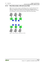
Page 60: ...ithout Access Point WEGs can be used to connect several LAN devices in an ad hoc WLAN If one WEG is connected per LAN device the WEGs can be configured for direct connection In this scenario all LAN devices integrated in the WLAN via WEG can communicate with each other and with any other WLAN subscribers Figure 29 Direct Connection without Access Point ...

Page 61: ...tive in the network DHCP Client or DHCP Client DHCP Relay can be set instead Wireless LAN Settings Network Name SSID Any SSID identical for all WEGs Wireless LAN Settings Operating Mode Ad Hoc Wireless LAN Settings Channel Any channel This setting must be identical for all WEGs Wireless LAN Settings Security multiple parameters Any settings identical for all WEGs Additional parameters may need to ...

Page 62: ...ed to integrate LAN devices in a WLAN managed by an access point If one WEG is connected per LAN device the WEGs can be configured for direct connection In this case the WEG acts as a wireless adapter When there is a radio link the respective LAN device can communicate with all other LAN or WLAN devices in the network of the access point Figure 30 Direct Connection with Access Point ...

Page 63: ...s Subnet Mask Any subnet mask that covers the range of IP addresses of all devices in the planned network e g 255 255 255 0 Network Settings IP Assignment Static when the IP address is to be set manually If a DHCP server is active in the network DHCP Client or DHCP Client DHCP Relay can be set instead Wireless LAN Settings Network Name SSID SSID of the access point Wireless LAN Settings Operating ...

Page 64: ...eliver a message from device A to device B and to return a response message immediately generated by device B to device A Application requirement Time permitted between sending a message and receiving a response Cycle time Property of the communication system Time that the communication system needs after receiving a message from device A before it can accept another message for transmission Appli...

Page 65: ...ms 1 Typical The specified time values are not exceeded in 99 of all messages sent 2 Maximum The specified time values are not exceeded in 99 9 of all messages sent Interference from other radio systems can worsen time responses Other radio systems that transmit data at the same time and frequency can significantly affect the time response The time response described cannot be achieved when the fr...

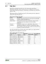
Page 66: ...nal quality If the signal is week or poor modulation methods must be used that permit slow data rates but a more stable connection Protocol efficiency Depending on the protocol administrative data must be transmitted in addition to user data The proportion of user data in regards to the total volume of data to be transmitted is a measure for protocol efficiency The following table shows example va...

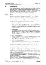
Page 67: ...e at the same location and in the same frequency range the signals can be differentiated and sorted out at the receiving device on the basis of the codes or frequency splitting techniques that are used 3 Space Division Multiplex As wireless technologies may only operated with limited transmitting power in the ISM band the transmitted signals become so weak at a certain distance that they no longer...

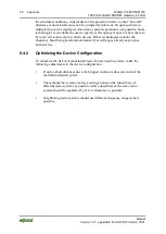
Page 68: ...ertain devices Other technologies monitor the frequency band being used and automatically avoid ranges already experience intensive use 8 4 2 Optimizing the Device Configuration To minimize the risk of mutual interference between radio systems make the following adjustments to the device configuration If only a short distances has to be bridged within a radio system limit the maximum transmit powe...

Page 69: ...haracteristic i e depending on the antenna alignment only highly amplified or extremely attenuated signals can be received The internal antenna of the WEG possesses an antenna gain of 5 dBi meaning that the reception properties can be greatly influenced by correct alignment Best results are achieved when the antenna front side of device is facing exactly in the direction from which the radio signa...

Page 70: ...ambient conditions vehicles movement of stored goods pedestrians These factors can make a precise prediction of the maximum range extremely difficult Effective path of radio waves is more significant than the actual distance Overcoming of maximum distances for a line of sight link is a scenario completely different from use inside rooms or in the direct vicinity to competing wireless technologies ...

Page 71: ...ia wireless communication 1 The attacker must be familiar with the communication system in use and be within the operating range of the system 2 Radio transmission must take place without the use of any security mechanisms offered by this technology or the attacker must have adequate means to determine the security code To minimize security risks choose the best security mechanisms available in th...

Page 72: ...gure 15 Connecting the WEG 30 Figure 16 Mode membrane button and status LEDs 33 Figure 17 Flow chart 35 Figure 18 WBM main page before login 40 Figure 19 WBM main page after login 41 Figure 20 WBM section Access Management 42 Figure 21 WBM section System Overview 42 Figure 22 WBM section Network Settings 43 Figure 23 WBM section Wireless LAN Settings 45 Figure 24 WBM section Miscellaneous 48 Figur...

Page 73: ...on System Overview 43 Table 18 WBM section Network Settings IP configuration 44 Table 19 WBM section Wireless LAN Settings Network 45 Table 20 WBM section Wireless LAN Settings General 46 Table 21 WBM section Wireless LAN Settings Security 46 Table 22 WBM section Wireless LAN Settings Client Mode 47 Table 23 AT Commands 50 Table 24 Bridge connection settings for 1st WEG 53 Table 25 Bridge connecti...

Page 74: ...WAGO Kontakttechnik GmbH Co KG Postfach 2880 D 32385 Minden Hansastraße 27 D 32423 Minden Phone 49 5 71 8 87 0 Fax 49 5 71 8 87 1 69 E Mail info wago com Internet http www wago com ...

Reviews: