30
Connect Devices
WAGO WINSTA® 770
770-629/130-000 WINSTA® Sunblind Box 4 Channel
Manual
Version 1.1.1, valid from HW/FW version XXXX0201XX
6.1.1.2
Central Operation with Voltage Monitoring
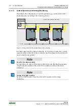
On principle, the configuration of a central operation (e.g. central switch, timer)
should take place according to the following scheme.
L / N / PE
230 V
AC
24 V
DC
Central Connection with Monitoring
Central Control
GND
up
down
Figure 12: Wiring of the Winsta sunblind boxes with monitoring
In central operation with voltage monitoring, 0V levels are evaluated as a control
signal. If neither of the 24V levels is detected, the drives linked to the system will
move toward the top position.
Heed the line dimensioning!
For the wiring of a system with central control, make sure that the dimensioning
(length and cross-section) of the control line is made according to the boxes
connected.
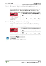
Setting of the DIP Switches
Switch 4 of DIP Module 2 must be activated for operation with voltage
monitoring.


