background image

WAGO WINSTA® 770 

Commissioning 

41 

770-629/130-000 WINSTA® Sunblind Box 4 Channel 


Manual 


Version 1.1.1, valid from HW/FW version XXXX0201XX 


7.4.6 

Setting the Operating Function (Sunblind/Slat Function) 

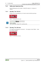
Set the operating function with switch 6 of the DIP module 2 to sunblind or slat 
function. 

7.4.6.1 

Sunblind Function 

To select sunblind operation, make the following settings: 

ON

DIP

1 2 3 4 5

6


Figure 29: Sunblind function 


Factory setting 

This is the factory setting for the operating logic. 


7.4.6.2 

Slat Function 

In order to set the operating function to slat operation, make the following 
settings: 

ON

DIP

1 2 3 4 5

6


Figure 30: Slat function 

Summary of Contents for 770-629/130-000

Page 1: ...Manual WAGO WINSTA 770 WINSTA Sunblind Box 4 Channel 770 629 130 000 Version 1 1 1 valid from HW FW version XXXX0201XX Pos 3 Alle Serien Allgemeine Module Hinweise zur Dokumentation Impressum allgemeine Angaben Anschriften Telefonnummern und E Mail Adressen 3 mod_1219151118203_21 doc 21060 1 ...

Page 2: ...0 571 8 87 5 55 Fax 49 0 571 8 87 85 55 E Mail support wago com Every conceivable measure has been taken to ensure the accuracy and completeness of this documentation However as errors can never be fully excluded we always appreciate any information or suggestions for improving the documentation E Mail documentation wago com We wish to point out that the software and hardware terms as well as the ...

Page 3: ...ion 12 3 1 View 13 3 2 Labeling 14 3 3 Connectors 15 3 3 1 Connection Overview 15 3 3 2 230V Supply 16 3 3 3 Motors 16 3 3 4 Local Push Buttons 17 3 3 5 Bus Central Connection 17 3 3 6 Screening 19 3 4 Display Elements 20 3 5 Operating Elements 20 3 5 1 DIP Switch Module 20 3 5 2 IDC Connectors for Jumper 21 3 6 Technical Data 22 3 6 1 General 22 3 6 2 Climatic Environmental Conditions 22 3 6 3 Su...

Page 4: ... 7 4 3 1 A Group Moving Motors 1 to 4 Simultaneously 37 7 4 3 2 Two Groups Moving Motors 1 and 2 and Motors 3 and 4 Simultaneously 37 7 4 3 3 Two Groups Moving Motors 1 2 and 3 Simultaneously Motor 4 Moves Individually 37 7 4 3 4 Three Groups Motors 1 and 2 Move Individually Motors 3 and 4 Move Simultaneously 38 7 4 3 5 Four Groups All Motors Move Individually 38 7 4 4 Setting of Bus Failure Monit...

Page 5: ...7_21 doc 46994 2 1 1 1 Scope of Validity This documentation applies to the WINSTA box 770 629 130 000 WINSTA Sunblind Box 4 Channel from HW FW version XXXX0201XX Pos 10 Serie 770 Winsta Boxen Hinweise zur Dokumentation Hinweis zur Dokumentation Winsta Box 0770 0629 6 mod_1260517445938_21 doc 46998 1 The WINSTA box 770 629 130 000 shall only be installed and operated according to the instructions i...

Page 6: ... if not avoided will result in death or serious injury Personal Injury Indicates a moderate risk potentially hazardous situation which if not avoided could result in death or serious injury Personal Injury Indicates a low risk potentially hazardous situation which if not avoided may result in minor or moderate injury Damage to Property Indicates a potentially hazardous situation which if not avoid...

Page 7: ...hannel Manual Version 1 1 1 valid from HW FW version XXXX0201XX Additional Information Refers to additional information which is not an integral part of this documentation e g the Internet Pos 11 4 Dokumentation allgemein Gliederungselemente Seitenwechsel 3 mod_1221108045078_0 doc 21810 1 ...

Page 8: ...5 Font Conventions Table 2 Font Conventions Font type Indicates italic Names of paths and data files are marked in italic type e g C Programme WAGO I O CHECK Menu Menu items are marked in bold letters e g Save A greater than sign between two names means the selection of a menu item from a menu e g File New Input Designation of input or optional fields are marked in bold letters e g Start of measur...

Page 9: ...1720 3 1 2 1 1 Subject to Changes WAGO Kontakttechnik GmbH Co KG reserves the right to provide for any alterations or modifications that serve to increase the efficiency of technical progress WAGO Kontakttechnik GmbH Co KG owns all rights arising from the granting of patents or from the legal protection of utility patents Third party products are always mentioned without any reference to patent ri...

Page 10: ...e Wichtige Erläuterungen Sicherheitshinweise Achtung Achtung Defekte oder beschädigte Geräte austauschen 6 mod_1260180857358_21 doc 46743 1 Replace defective or damaged devices Replace defective or damaged device module e g in the event of deformed contacts since the long term functionality of device module involved can no longer be ensured Pos 14 8 6 Alle Serien Allgemeine Module Wichtige Erläute...

Page 11: ...id electrostatic discharge The devices are equipped with electronic components that you may destroy by electrostatic discharge when you touch Pay attention while handling the devices to good grounding of the environment persons job and packing Pos 15 Dokumentation allgemein Gliederungselemente Seitenwechsel 3 mod_1221108045078_0 doc 21810 1 ...

Page 12: ...and slat sunblind mode selection are performed via DIP switch Operating the boxes in a network configuration provides extended functionality 1 The sunblinds of all connected boxes can optionally be moved into the upper or lower end position via a central 24V control line Either a weather station a timer or a central switch enables this functionality 2 2 The boxes also connect to a serial bus allow...

Page 13: ... S2 S3 S4 1 2 N 1 2 N N 2 1 N 2 1 N L 4 3 2 1 1 2 3 4 5 6 ON DIP 1 2 3 4 5 6 ON DIP 1 2 3 4 5 6 ON DIP S6 S5 S7 230 V Jumper 8 7 10 10 10 10 1 2 3 9 4 5 6 2 7 7 7 Figure 1 View Table 3 Legend for View figure No Designation Description 1 Housing 2 Assembly fitting points 3 S5 DIP module 1 bus addresses 4 S6 DIP module 2 operating functions 5 S7 IDC connector jumper selection of the control bus cent...

Page 14: ...ice designation the most important device data the marking field for the address the serial number and the pin assignments for the connectors Marking field for address To make identification even easier enter the set bus address in the address field The serial number indicates the delivery status directly after production This number consists of the week and year of manufacture the software versio...

Page 15: ...40984262656_21 doc 31961 2 1 3 3 Connectors Pos 26 Serie 770 Winsta Boxen Gerätebeschreibung Anschlüsse Anschlüsse 0770 0629 0130 0000 6 mod_1255677975461_21 doc 42970 333333 1 3 3 1 Connection Overview DIP Modul 2 DIP Modul 1 230 V M4 M3 M2 M1 S1 S2 S3 S4 1 2 N 1 2 N N 2 1 N 2 1 N L 4 3 2 1 1 2 3 4 5 6 ON DIP 1 2 3 4 5 6 ON DIP 1 2 3 4 5 6 ON DIP Jumper S6 S5 S7 N N NC A B NC GND NC N N N L M M M...

Page 16: ...or with the designation 230 V The connection is fused with a 6 3 A fuse Table 4 Connection of 230V supply Connection Designation Function L L PE PE L PE N L PE N WAGO 770 103 WAGO 770 103 Figure 5 Connection of 230V supply N N 3 3 3 Motors The motors are each connected to the box via a four pole plug M1 to M4 here a uniform rotational direction connection and the correct operation direction must b...

Page 17: ... The type of activation of the box can be selected with the help of an IDC connector jumper At the factory bus operation activation via RS485 signal is pre set Alternatively by changing the jumper it is possible to select central operation activation via 24V DC control signal The setting of the jumper is described in the chapter Putting into operation Setting bus or central operation In bus operat...

Page 18: ...nnection Designation Bus Central 1 B N C 2 A GND 3 N C Down 1 2 3 4 1 2 3 4 WAGO 770 244 Buchse 770 504 023 Gehäuse WAGO 770 244 Buchse 770 504 023 Gehäuse Figure 8 Bus central connection 4 N C Up Activation via the WAGO I O SYSTEM 750 The following module is required to activate via bus signal RS485 and WAGO I O SYSTEM RS 485 serial interface adjustable item number 750 653 003 000 ...

Page 19: ...l The screening should be laid at the entrance to the cabinet or housing in order to catch interference right at the entrance The screening of the bus line is described in the respective configuration guidelines and standards of the bus system RS485 specification Lay the screening so that its area is as large as possible Improved screening is achieved if the large area screening is applied This is...

Page 20: ...le Serien Allgemeine Module Überschriften für alle Serien Bedienelemente Überschrift 2 4 mod_1239191655456_21 doc 30439 2 1 3 5 Operating Elements Pos 31 Serie 770 Winsta Boxen Gerätebeschreibung Bedienelemente Bedienelemente 0770 0629 0130 0000 6 mod_1256894169678_21 doc 43990 33 1 3 5 1 DIP Switch Module The sunblind box has two DIP switch modules that can be used to make different settings DIP ...

Page 21: ...The sunblind box has an IDC connector for a jumper bridge with which it is possible to select whether the box should be activated via a bus signal RS485 or via a 24V signal central operation DIP Modul 2 4 3 2 1 ON DIP ON DIP S7 Jumper Figure 10 IDC connector for jumper bridge Pos 32 Dokumentation allgemein Gliederungselemente Seitenwechsel 3 mod_1221108045078_0 doc 21810 1 ...

Page 22: ... General Dimensions W x H x D without connector plug 200 mm x 145 mm x 30 mm Weight 450 g Type of mounting Wall screw fixing Assembly Interior area e g intermediate floors suspended ceiling Fitting position any Degree of protection IP 20 Pollution degree 2 Housing material Polyamide PA 6 6 flammability class UL94 V 0 3 6 2 Climatic Environmental Conditions Table 10 Technical data Environmental con...

Page 23: ...ransmission medium Control line J Y St Y 2 x 2 x 0 6 mm2 max 10 m Connection type Female connector 3 pole Item No 734 103 Snap on strain relief housing Item No 734 603 3 6 5 Outputs Table 13 Technical data Outputs No of outputs 4 power outputs for motors up down locked against each other Switching voltage 230 V AC Switching current 4 x 1 5 A at 230 V AC Switching power 300 W AC3 per motor Connecti...

Page 24: ...te 9 600 baud Max number of bus participants 16 Transmission medium Screened bus cable YCYM 2 x 2 x 0 8 mm2 max 800 m Central control via 24VDC signal Operating voltage DC 24 V 10 50 Current consumption max 5 mA Transmission medium Screened bus line YCYM 2 x 2 x 0 8 mm2 3 6 7 Setting and Operating Units Table 15 Technical data Setting and operating units S5 DIP module 1 Setting of bus addresses S6...

Page 25: ...755687_0 doc 24460 1 Pos 40 Alle Serien Allgemeine Module Überschriften für alle Serien Normen und Richtlinien Überschrift 2 4 mod_1242804031875_21 doc 33646 2 1 3 8 Standards and Guidelines Pos 41 Serie 770 Winsta Boxen Gerätebeschreibung Normen und Richtlinien EMV Normen 0770 0629 7 mod_1268229464774_21 doc 52248 1 The WINSTA sunblind box 770 629 130 000 complies with the following EMC standards...

Page 26: ...50 653 003 000 via which the WAGO I O SYSTEM as the superior controller can access up to 16 boxes per bus segment This operating mode addresses both individual channels and groups of boxes Additional information about programming For additional information about programming and the possible functions see www wago com Downloads Building automation When bus failure monitoring is activated the drives...

Page 27: ...function is suitable for interior or exterior blinds whose slats can be adjusted horizontally in order to regulate light coming in e g classic sun protection The sunblind moves in the desired direction while the push button is pressed If the push button is pressed for longer than 0 5 seconds the controller goes into lock The push button can then be released the sunblind will move until the set run...

Page 28: ...rew holes Pos 50 Alle Serien Allgemeine Module Überschriften für alle Serien Geräte anschließen Überschrift 1 3 mod_1234172889468_21 doc 27460 1 1 6 Connect Devices Pos 51 Serie 770 Winsta Boxen Anschließen Anschließen 0770 0629 0130 0000 7 mod_1271851277981_21 doc 55503 1 The following plug connectors are required to connect the sunblind box not included in the scope of delivery A plug set with t...

Page 29: ...ation without Voltage Monitoring On principle the configuration of a central operation e g central switch timer should take place according to the following scheme L N PE 230 V AC 24 V DC Central Connection Standard Central Control GND up down Figure 11 Wiring of the Winsta sunblind boxes for conventional 24 V control In central operation without voltage monitoring 24V levels are evaluated as a co...

Page 30: ...ral Control GND up down Figure 12 Wiring of the Winsta sunblind boxes with monitoring In central operation with voltage monitoring 0V levels are evaluated as a control signal If neither of the 24V levels is detected the drives linked to the system will move toward the top position Heed the line dimensioning For the wiring of a system with central control make sure that the dimensioning length and ...

Page 31: ...me B 120 W L N PE A 120 W Bus Connection Central Control Figure 13 Wiring of the Winsta sunblind boxes in a bus system Don t forget the bus end module The bus must be connected at the beginning and end to a 120 Ω resistor Operation via bus signal RS485 The following module is required to operate via bus signal RS 485 and WAGO I O System WAGO I O adjustable RS485 module 750 653 003 000 Pos 55 Dokum...

Page 32: ...anges to these settings will be explained below Only make the setting when the device is de energized In order not to damage the sunblind box settings on the box shall only be made when it is de energized Changes to the setting only become effective after a restart For safety reasons a change to a setting may only be taken over after a restart of the box This takes place automatically when the sun...

Page 33: ...S485 or via a 24V signal central operation DIP Modul 2 4 3 2 1 ON DIP ON DIP S7 Jumper Figure 14 IDC connector for jumper bridge 7 3 1 Bus Operation If the jumper bridge is plugged in the viewing direction of the figure above into the two lower pins bus activation is selected Figure 15 Jumper setting for bus operation Factory setting This is the factory setting for the activation type Setting the ...

Page 34: ...X 7 3 2 Central Operation If the jumper bridge is plugged in the viewing direction of the figure above into the two upper pins 24V activation is selected S3 Figure 16 Jumper setting for central operation Setting of Address 0 For Central operation de activate switches 1 to 5 of DIP Module 1 address 0 see Section Setting the Bus Address ...

Page 35: ...rouping of the motors the moving time and the moving logic DIP Modul 2 DIP Modul 1 M3 4 3 2 1 1 2 3 4 5 6 ON DIP 1 2 3 4 5 6 ON DIP 1 2 3 4 5 6 ON DIP S6 Jumper S7 S5 Figure 17 DIP switch module 7 4 1 Setting of the DIP Switches For the settings the following conventions apply Table 16 Setting of the DIP switches View Meaning White field Position of the switch Grayed out Not relevant ON DIP 2 6 1 ...

Page 36: ...e setting of bus addresses is only possible in bus operation For Central operation de activate switches 1 to 5 of DIP Module 1 address 0 Set the bus address with the switches 1 to 5 of the DIP module 1 ON DIP 0 1 2 3 4 5 6 7 8 9 10 11 12 13 14 15 16 Adr DIP Figure 19 Setting of the bus address To make identification in bus operation even easier you can write the set address in the corresponding fi...

Page 37: ... Motors 1 and 2 and Motors 3 and 4 Simultaneously To form two groups Group A in which motors 1 and 2 and Group B in which motors 3 and 4 move together make the following settings Table 18 Two groups motors 1 and 2 and motors 3 and 4 move simultaneously Assignment of motors local push buttons Motor 1 2 3 4 ON DIP 1 2 3 4 5 6 ON DIP 2 3 4 5 6 1 Figure 21 Two groups motors 1 and 2 and motors 3 and 4 ...

Page 38: ...d 4 move simultaneously Assignment of motors local push buttons Motor 1 2 3 4 ON DIP 1 2 3 4 5 6 ON DIP 1 2 3 4 5 6 Figure 23 Three groups motors 1 and 2 move individually motors 3 and 4 move simultaneously Push button S1 S2 S3 S3 7 4 3 5 Four Groups All Motors Move Individually In order to have each connected motor move individually make the following settings Table 21 Four groups all motors move...

Page 39: ...ing Make the following settings to activate bus failure monitoring voltage monitoring ON DIP 1 2 3 4 5 6 Figure 26 Operation with bus failure monitoring voltage monitoring Voltage Monitoring in Central Operation At this setting the switching logic is changed from 2 x make contact elements to 2 x break contact elements This enables both signals to be monitored The drives linked to the system move i...

Page 40: ...minute or 4 minutes 7 4 5 1 Operating Time 1 Minute In order to set an operating time of 1 minute make the following settings ON DIP 1 2 3 4 5 6 Figure 27 Operating time 30 seconds Factory setting This is the factory setting for the operating time 7 4 5 2 Operating Time 4 Minutes To extend the operating time to 4 minutes for example for door blinds make the following settings ON DIP 1 2 3 4 5 6 Fi...

Page 41: ...nction with switch 6 of the DIP module 2 to sunblind or slat function 7 4 6 1 Sunblind Function To select sunblind operation make the following settings ON DIP 1 2 3 4 5 6 Figure 29 Sunblind function Factory setting This is the factory setting for the operating logic 7 4 6 2 Slat Function In order to set the operating function to slat operation make the following settings ON DIP 1 2 3 4 5 6 Figure...

Page 42: ...s necessary The positions are lost in case of a power failure After a loss of supply voltage all stored sunblind positions are lost After a completely executed reference operation to any end position the controller stores the sunblind position internally Behavior after power failure in bus operation After a power failure it can take up to 1 minute until the WAGO I O SYSTEM has recorded the box aga...

Page 43: ...372 1 1 8 Diagnostics Pos 60 Serie 770 Winsta Boxen Diagnose Diagnose 0770 0629 0130 0000 7 mod_1268228638180_21 doc 52231 1 Diagnosis can be undertaken with the function module FbWinsta_BC_Box Additional diagnostic information For additional information see the module description for the WINSTA sunblind box at www wago com Downloads Building automation Pos 61 Dokumentation allgemein Gliederungsel...

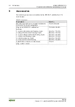
Page 44: ... 770 629 130 000 Table 22 Accessories Description Item No RS 485 serial interface for modular WAGO I O SYSTEM 750 freely configurable 750 653 003 000 Plug set for WINSTA sunblind box Includes 1 x socket with strain relief housing 3 pole 4 x plug with strain relief housing 4 pole 1 x socket without strain relief housing 4 pole 1 x strain relief housing 4 pole 4 x female connector 3 pole 4 x snap on...

Page 45: ...sunblind boxes in a bus system 31 Figure 14 IDC connector for jumper bridge 33 Figure 15 Jumper setting for bus operation 33 Figure 16 Jumper setting for central operation 34 Figure 17 DIP switch module 35 Figure 18 Setting of the DIP switches 35 Figure 19 Setting of the bus address 36 Figure 20 One group motors 1 to 4 move simultaneously 37 Figure 21 Two groups motors 1 and 2 and motors 3 and 4 m...

Page 46: ...Technical data General 22 Table 10 Technical data Environmental conditions 22 Table 11 Technical Data Supply 22 Table 12 Technical data Inputs 23 Table 13 Technical data Outputs 23 Table 14 Technical data Control 24 Table 15 Technical data Setting and operating units 24 Table 16 Setting of the DIP switches 35 Table 17 One group motors 1 to 4 move simultaneously 37 Table 18 Two groups motors 1 and ...

Page 47: ...NSTA 770 47 770 629 130 000 WINSTA Sunblind Box 4 Channel Manual Version 1 1 1 valid from HW FW version XXXX0201XX Pos 69 Dokumentation allgemein Gliederungselemente Leerseite 3 mod_1219230851078_0 doc 21123 1 ...

Page 48: ...9 mod_1285229376516_21 doc 64944 1 WAGO Kontakttechnik GmbH Co KG Postfach 2880 D 32385 Minden Hansastraße 27 D 32423 Minden Phone 49 5 71 8 87 0 Fax 49 5 71 8 87 1 69 E Mail info wago com Internet http www wago com Ende der Liste für Textmarke Einband_hinten ...

Reviews: