


38
Mounting
EPSITRON® COMPACT Power
787-1202 / -1212 / -1216 / -1226 EPSITRON® COMPACT Power
Manual
Version 1.0.0
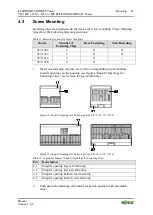
3.
Gently shake the fastening clip to verify that it is fitted securely.
4.
Fasten the device with the appropriate M4 screws (not included).
Observe the maximum torque of 2.9 Nm.
The exact dimensions and positions of the fastening clips are provided on the
drilling templates supplied with the device.
Pos: 46 /D okumentation allgemei n/Glieder ungselemente/---Seitenwechsel--- @ 3\mod_1221108045078_0.docx @ 21810 @ @ 1


