18 Device Description
Compact Power
787-1211 DC power supply, 12 V
Manual
Version 1.
1
.0
P o s : 2 4 /A lle S e rie n ( A llg e m ein e M o d ule ) /Ü b er sc h rif te n /E be n e 2 /A ns c hlü s s e - Ü b e rs ch rif t 2 @ 4 \ m od _ 12 4 09 8 4 26 2 65 6 _2 1 .d o cx @ 31 9 61
@ 2 @ 1
3.3
Connectors
P o s :
2 5 . 1 /A lle S e rie n ( A llg e m ein e M o d ule ) /S ic h er he it s- u n d so n st ig e H
in w e is e /G e fa hr /G e fa h r: N ich t a n G er ät en u n te r Sp a n nu n g ar b eit e n!
@ 6\ m od _ 12 6 01 8 0 36 5 32 7 _2 1 .d o cx @ 46 7 2 7 @ @ 1
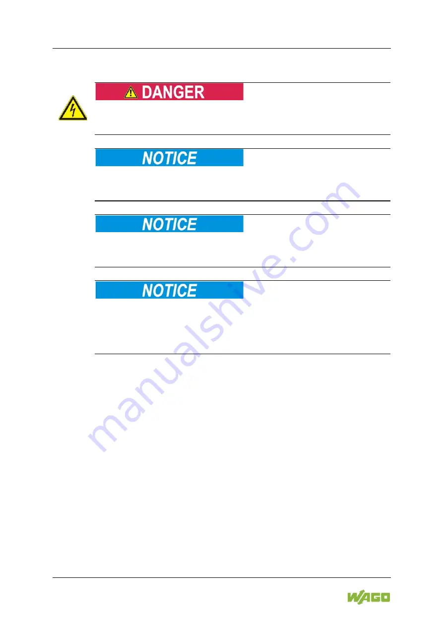
Do not work on devices while energized!
All power sources to the device shall be switched off prior to performing any
installation, repair or maintenance work.
P o s : 2 5 . 2 /S e rie 7 8 7 (E P S IT R O N
) /Wic h tig e E r lä ut er un g e n/ Sic h e rh e its - un d s on s tig e H in w eis e /A c h tu ng /A c ht u ng : Fe d er le is te n n ich t u nt er L as t st ec k en o d er z ie h en ! @ 1 8 \m o d_ 1 39 2 9 00 2 17 4 63 _ 2 1. do c x @ 1 4 59 4 1 @ @ 1
Do not plug in or disconnect the female connector while a load is applied!
Only plug in or disconnect the female connectors when the device is not live!
Failure to observe this can result in damage to the contacts due to arcing!
P o s : 2 5 . 3 /S e rie 7 8 7 (E P S IT R O N
) /Wic h tig e E r lä ut er un g e n/ Sic h e rh e its - un d s on s tig e H in w eis e /A c h tu ng /A c ht u ng : Fe d er le is te n b is zu m A n s ch la g in d ie S tif tle is t en s te c ke n ! @ 1 8\ m o d_ 1 39 2 90 2 88 9 0 21 _ 21 .d o cx @ 1 45 9 44 @ @ 1
Plug the female connectors all the way into the male connectors!
Always plug the female connectors all the way in to the male connectors. This
ensures proper contact at all times.
P o s : 2 5 . 4 /S e rie 7 8 7 (E P S IT R O N
) /Wic h tig e E r lä ut er un g e n/ Sic h e rh e its - un d s on s tig e H in w eis e /A c h tu ng /A c ht u ng : Fr eis c h w in ge n de L e ite r en d en d u rc h e ine
ge e ig ne te Z u g en tla s tu n g ab fa n ge n ! @ 1 8 \m o d_ 1 39 2 9 04 2 62 7 58 _ 21 . do c x @ 1 46 0 0 8 @ @ 1
Attach the free ends of the conductors using a strain relief device!
Female connectors can be pulled out of the male connectors by high vibration
levels or shock impacts!
Provide appropriate strain relief means to attach and cap any free ends of the
conductors!
P o s : 2 5 . 5 /S e rie 7 8 7 (E P S IT R O N
) /G e rä te b es c hr e ibu n g /A ns c hlü s s e/ An s ch lü s se 7 8 7- 1 2x x @ 19 \m o d _1 3 97 6 5 04 4 98 4 4_ 2 1. d oc x @ 1 5 1 89 9 @ 34 4 @ 1
3.3.1
Connectors
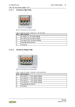
The supply lines are connected on the input and output side using the 2092
Series WAGO
picoMAX
®
pluggable connectors:
•
Input side:
picoMAX
®
5.0
•
Output side:
picoMAX
®
5.0
Observe the maximum admissible conductor cross sections for the signal and
power cables (see section “Device Description” > “Technical Data”).
Check the appropriate operating voltage before connecting equipment (see type
plate).
Additional information on the connection technology is provided in the section
“Connecting Devices.”

