Compact Power
Mounting 41
787-1211 DC power supply, 12 V
Manual
Version 1.
1
.0
P o s :
4 5 . 11 / S er ie 7 87 ( E PS I TR O N ) /M o nt ie re n/ M o nt ag e 7 87 - 12 x 1 - S c h ra ub b ef es tig u n g @ 3 2 \m o d _1 5 33 5 33 1 3 38 3 3_ 2 1. do c x @ 4 9 30 7 9 @ 2 @ 1
4.3
Screw Mounting
Fastening clips are supplied with the device for screw mounting. These fastening
clips allow the screw mounting.
1.
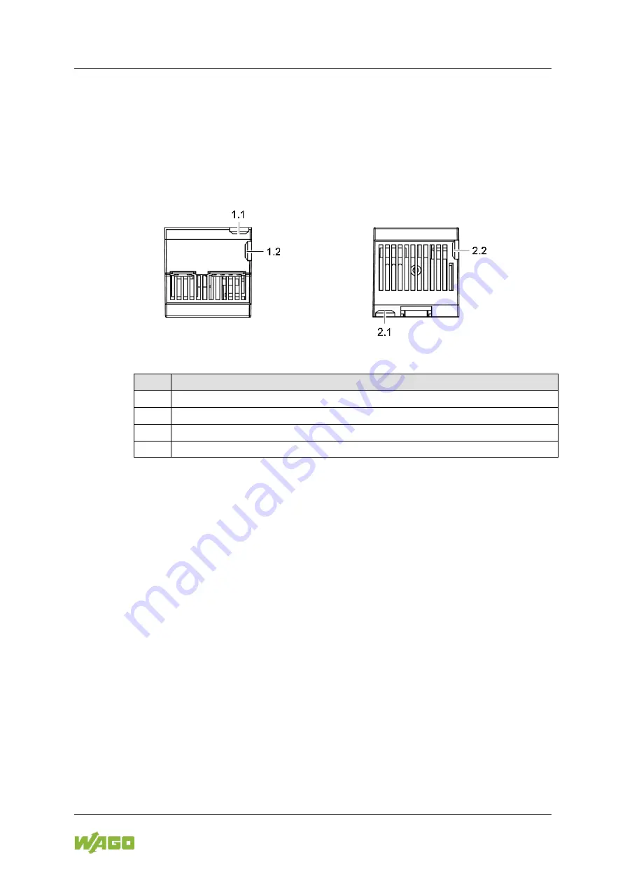
Insert one fastening clip into each of the corresponding top and bottom
snap-fit openings on the housing (see figures “Snap-fit Openings for
Fastening Clips,” views from the top and bottom).
Figure 17: Snap-fit Openings for Fastening Clips
Table 27: Legend for Figures “Snap-fit Openings for Fastening Clips”
Pos. Description
1.1
Snap-fit opening top; rear fastening
1.2
Snap-fit opening top; side fastening
2.1
Snap-fit opening bottom; rear fastening
2.2
Snap-fit opening bottom; side fastening
2.
Push down the fastening clip until it locks into position with an audible click.
3.
Gently shake the fastening clip to verify that it is fitted securely.
4.
Fasten the device with the appropriate M4 screws (not included).
Observe the maximum torque of 2.9 Nm.
The exact dimensions and positions of the fastening clips are provided on the
drilling templates supplied with the device.
P o s : 4 6 /D o ku m e nt at io n allg e m e in /G lie d e ru n g se le m e nt e/ --- S eit e nw e c hs e l-- - @ 3 \m o d _1 2 21 1 08 0 4 50 7 8_ 0 .d oc x @ 21 8 10
@ @ 1

