90
• Feldbus Coupler/Controller
Fieldbus Controller 750-806
WAGO-I/O-SYSTEM 750
DeviceNet
750-550 2 channel analog output
4 bytes output
750-600 end module
-
-
PFC fieldbus input variables
0 bytes input
PFC fieldbus output variables
4 bytes output
Sum
10 bytes
6 bytes
Note
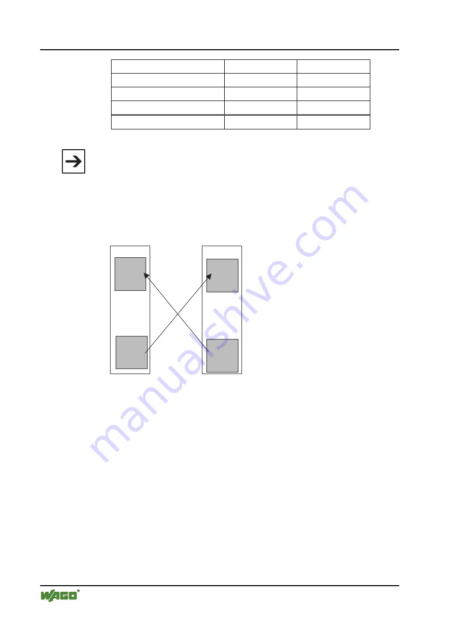
PFC output variables are defined from the point of view of the programmable
fieldbus Controller. These are input variables from the point of view of the
fieldbus DeviceNet, which are added to the RX Settings. Accordingly, PFC
input variables are output variables for IEC 61131-3 access of the field bus.
For that reason they will be added to the TX Settings:
IEC 61131-3 input variable
= PFC output variable
PFC input variable
= IEC 61131-3 output variable
PFC-
Eingangs-
variablen
PFC-
Ausgangs-
variablen
Programmierbarer
Feldbus Controller
Feldbus
SPS-
Eingangs-
variablen
SPS-
Ausgangs-
variablen
Fig. 3-33: Zusammenhang SPS-Variablen and PFC-Variablen
g012444d
4. Static assembly for inputs
In the present example, the master/scanner is to have access to the physical in-
puts and to the 4 bytes PFC output variables.
The number of input data is complemented by 4 bytes of the PFC output vari-
ables during the static assembly for the TX configuration of the scanner.
1.
To be able to parameterize the Controller, double-click on the graphic
symbol of the fieldbus node 750-806.
2.
In the "General" register, you can assign the Controller any desired ad-
dress.
To this effect, click in the input window for the address and enter the ad-
dress in accordance with the address set at the Controller DIP switch.
3.
The RX/TX configuration can be entered in the "Parameters" register. For
this purpose, move to the "Groups" dialog box, down along the scroll bar,
and select "PLC fieldbus variables".


