WAGO-I/O-SYSTEM 750
I/O Modules 129
750-306 DeviceNet
TM
Fieldbus Coupler
Manual
Version 2.0.0
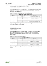
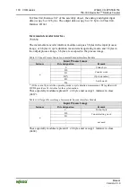
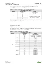
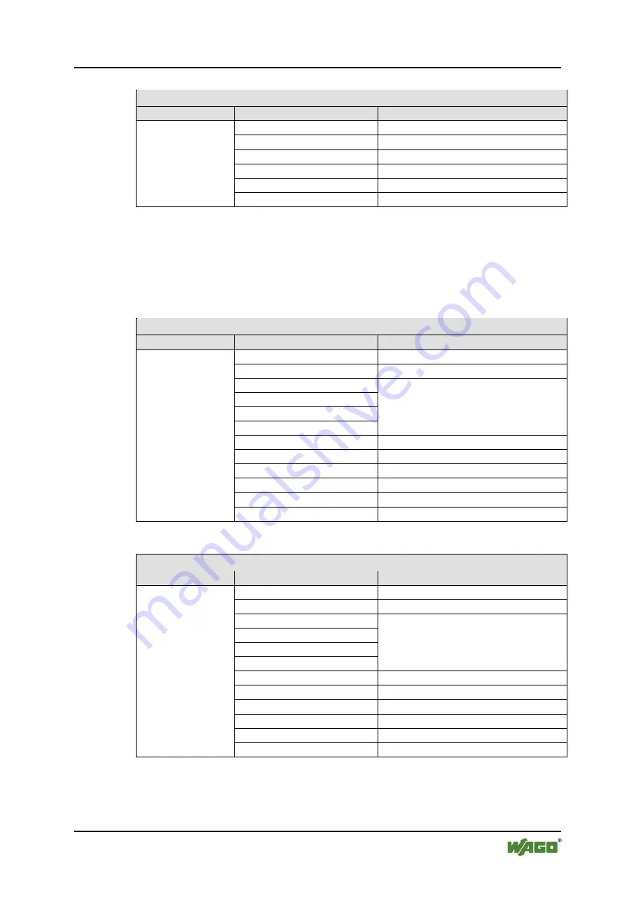
Table 120: Output Process Image, Proportional Valve Module
Output process image
Instance
Byte designation
Remark
n
C0
Control byte
MBX_CTRL
Mailbox control byte
MBX_DATA
Mailbox data
V1_CONTROL
Valve 1 control
V1_SETPOINTVALUE_L
Valve 1, target value, low byte
V1_SETPOINTVALUE_H
Valve 1, target value, high byte
These specialty modules represent 1 x 6 bytes and occupy 1 instance in class
(0x67) and 1 instance in class (0x68).
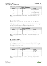
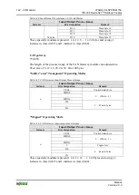
2-channel mode
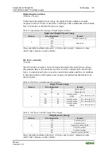
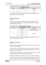
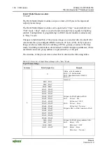
Table 121: Proportional Valve Module Input Process Image
Input Process Image
Instance
Byte designation
Remark
n
S0
Status byte
MBX_ST
Mailbox status byte
MBX_DATA1
Mailbox data
MBX_DATA2
MBX_DATA3
MBX_DATA4
V1_STATUS
Valve 1 control
V2_STATUS
Valve 2 control
V1_ACTUAL_L
Valve 1, actual value, low byte
V1_ACTUAL_H
Valve 1, actual value, low byte
V2_ACTUAL_L
Valve 2, actual value, low byte
V2_ACTUAL_H
Valve 2, actual value, low byte
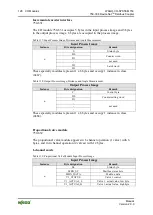
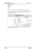
Table 122: Output Process Image, Proportional Valve Module
Output process image
Instance
Byte designation
Remark
n
C0
Control byte
MBX_CTRL
Mailbox control byte
MBX_DATA1
Mailbox data
MBX_DATA2
MBX_DATA3
MBX_DATA4
V1_CONTROL
Valve 1 control
V2_CONTROL
Valve 2 control
V1_SETPOINTVALUE_L
Valve 1, target value, low byte
V1_SETPOINTVALUE_H
Valve 1, target value, high byte
V2_SETPOINTVALUE_L
Valve 2, target value, low byte
V2_SETPOINTVALUE_H
Valve 2, target value, high byte
These specialty modules represent 1 x 12 bytes and occupy 1 instance in class
(0x67) and 1 instance in class (0x68).


