WAGO-I/O-SYSTEM 750
I/O Modules 131
750-306 DeviceNet
TM
Fieldbus Coupler
Manual
Version 2.0.0
Digital impulse interface
750-635, 753-635
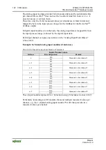
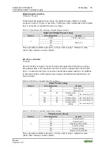
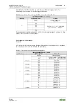
In the input and output process image, the digital impulse interface module
occupies a total of 4 bytes of user data: 3 data bytes and 1 additional control/status
byte. 4 bytes are occupied in the process image.
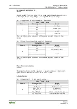
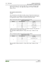
Table 125: Input/Output Process Image, Digital Impulse Interface
Input and Output Process Image
Instance
Byte designation
Remark
n
C0/S0
Control/status byte
D0
Data bytes
D1
D2
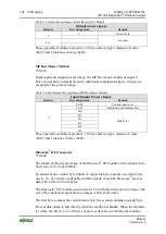
These specialty modules represent 1 x 4 bytes and occupy 1 instance in class
(0x67) and 1 instance in class (0x68).
DC drive controller
750-636
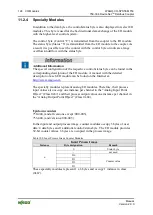
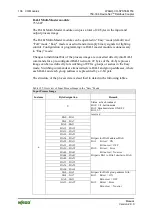
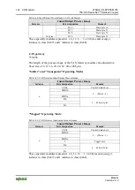
The I/O module occupies 6 bytes of input and output data in the process image.
The position data to be sent and received is stored in 4 output bytes and 4 input
bytes. 2 control/status bytes are used to control the module and drive. In addition
to the position data in the input process image, extended status information can
also be shown.
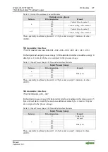
Table 126: DC Drive Controller Input Process Image
Input Process Image
Instance
Byte designation
Remark
n
S0
Status byte S0
S1
Status byte S1
D0
S2
Actual position
(LSB)
Ext. status byte S2
D1
S3
Actual position
Ext. status byte S3
D2
S4
Actual position
Ext. status byte S4
D3
S5
Actual position
(MSB)
Ext. status byte S5
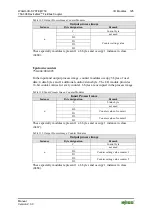
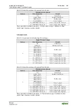
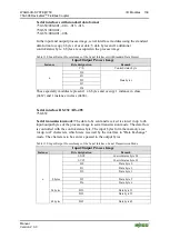
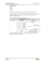
Table 127: DC Drive Controller Output Process Image
Output process image
Instance
Byte designation
Remark
n
C0
Control byte C0
C1
Control byte C1
D0
Setpoint position (LSB)
D1
Setpoint position
D2
Setpoint position
D3
Setpoint position (MSB)
These specialty modules represent 1 x 6 bytes and occupy 1 instance in class
(0x67) and 1 instance in class (0x68).

