136 I/O Modules
WAGO-I/O-SYSTEM 750
750-306 DeviceNet
TM
Fieldbus Coupler
Manual
Version 2.0.0
DALI Multi-Master module
753-647
The DALI Multi-Master module occupies a total of 24 bytes in the input and
output process image.
The DALI Multi-Master module can be operated in “Easy” mode (default) and
“Full” mode. "Easy" mode is used to transmit simply binary signals for lighting
control. Configuration or programming via DALI master module is unnecessary
in “Easy” mode.
Changes to individual bits of the process image are converted directly into DALI
commands for a pre-configured DALI network. 22 bytes of the 24-byte process
image can be used directly for switching of ECGs, groups or scenes in the Easy
mode. Switching commands are transmitted via DALI and group addresses, where
each DALI and each group address is represented by a 2-bit pair.
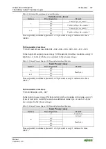
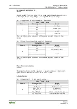
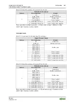
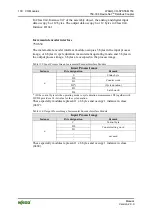
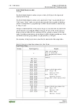
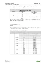
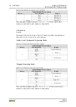
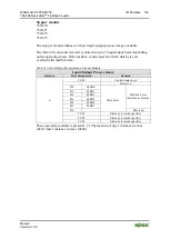
The structure of the process data is described in detail in the following tables.
Table 155: Overview of Input Process Image in the “Easy” Mode
Input Process Image
Instance
Byte designation
Remark
n
S
Status, active broadcast:
Bit 0: 1-/2-button mode
Bit 2: Broadcast status ON/OFF
Bit 1,3-7: -
-
reserved
DA0…DA3
DA4…DA7
DA8…DA11
DA12…DA15
DA16…DA19
DA20…DA23
DA24…DA27
Bit pair for DALI address DA0:
DA28…DA31
Bit 1:
Bit set = ON
DA32…DA35
Bit not set = OFF
DA36…DA39
Bit 2:
Bit set = Error
DA40…DA43
Bit not set = No error
DA44…DA47
Bit pairs DA1 to DA63 similar to DA0.
DA48…DA51
DA52…DA55
DA56…DA59
DA60…DA63
GA0…GA3
Bit pair for DALI group address GA0:
GA4…GA7
Bit 1: Bit set = ON
GA8…GA11
Bit not set = OFF
GA12…GA15
Bit 2: Bit set = Error
Bit not set = No error

