WAGO-I/O-SYSTEM 750
I/O Modules 137
750-306 DeviceNet
TM
Fieldbus Coupler
Manual
Version 2.0.0
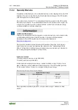
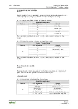
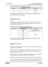
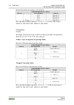
Table 155: Overview of Input Process Image in the “Easy” Mode
Input Process Image
Instance
Byte designation
Remark
-
Not used
-
DA = DALI address
GA = Group address
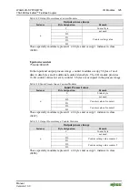
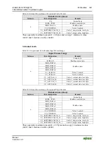
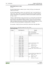
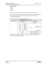
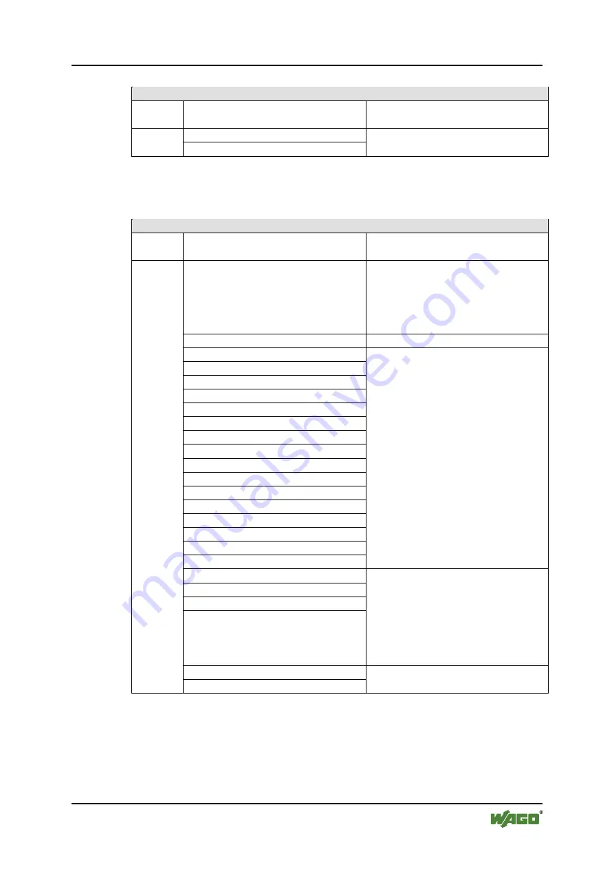
Table 156: Overview of the Output Process Image in the “Easy” mode
Input Process Image
Instance
Byte designation
Remark
n
C
Broadcast ON/OFF and activate:
Bit 0: Broadcast ON
Bit 1: Broadcast OFF
Bit 2: Broadcast ON/OFF/dimming
Bit 3: Broadcast short ON/OFF
Bit 4…7: reserved
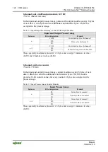
-
reserved
DA0…DA3
DA4…DA7
DA8…DA11
DA12…DA15
DA16…DA19
DA20…DA23
DA24…DA27
Bit pair for DALI address DA0:
DA28…DA31
Bit 1:
short: DA switch ON
DA32…DA35
long: dimming, brighter
DA36…DA39
Bit 2:
short: DA switch OFF
DA40…DA43
long: dimming, darker
DA44…DA47
Bit pairs DA1 to DA63 similar to DA0.
DA48…DA51
DA52…DA55
DA56…DA59
DA60…DA63
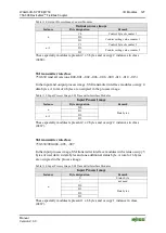
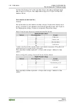
GA0…GA3
Bit pair for DALI group address GA0:
GA4…GA7
Bit 1: short: GA switch ON
GA8…GA11
long: dimming, brighter
GA12…GA15
Bit 2: short: GA switch OFF
long: dimming, darker
Bit pairs GA1 to GA15 similar to GA0.
Bit 0…7
Switch to scene 0…15
Bit 8…15
DA = DALI address
GA = Group address
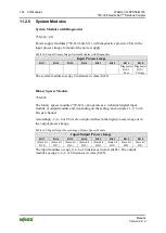
These specialty modules represent 1 x 24 bytes and occupy 1 instance in class
(0x67) and 1 instance in class (0x68).


