140 I/O Modules
WAGO-I/O-SYSTEM 750
750-306 DeviceNet
TM
Fieldbus Coupler
Manual
Version 2.0.0
Data exchange mode:
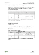
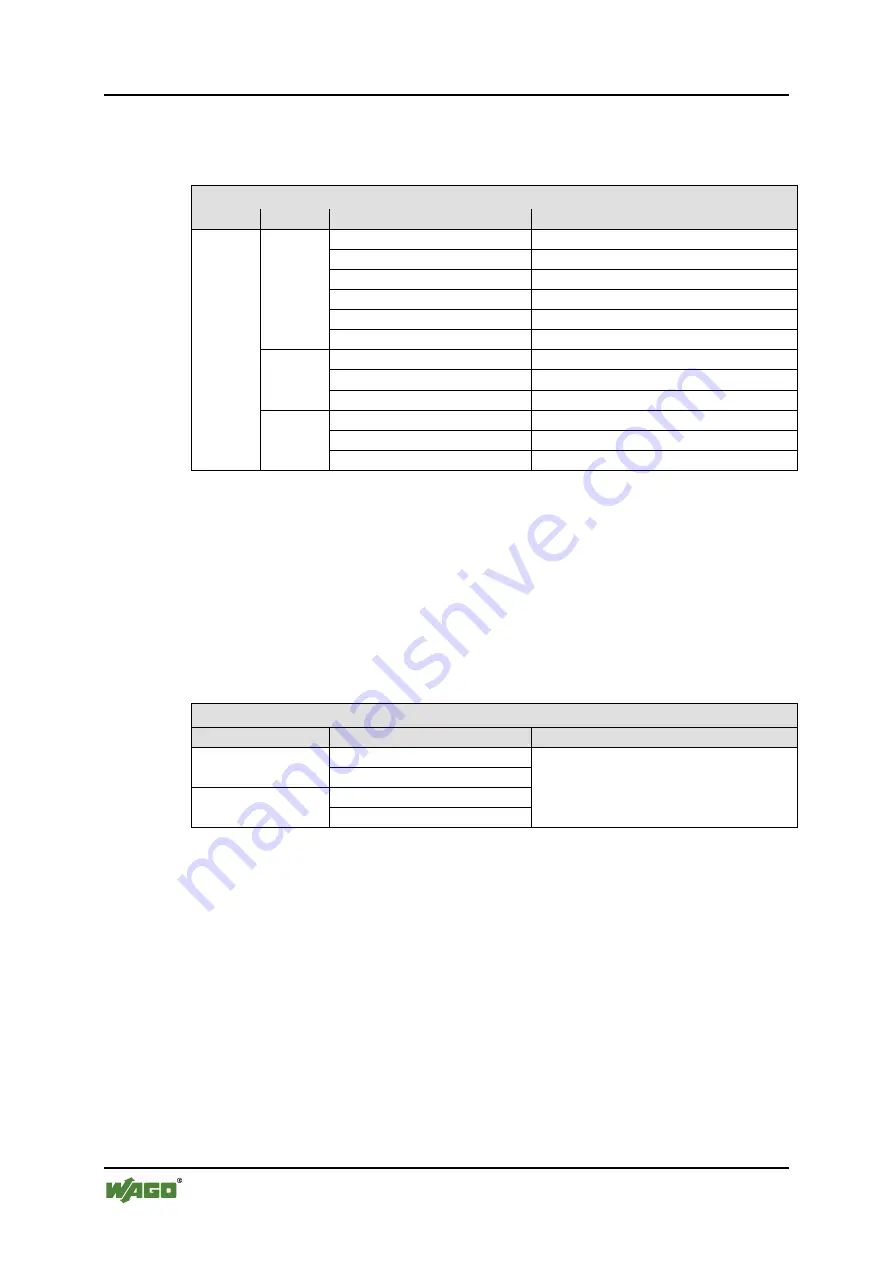
The data to be sent and received is stored in up to 47 input
and output bytes. The data flow is controlled with the control/status byte.
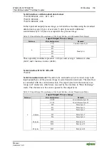
Table 140: Input/Output Process Image of the Serial Interface, Data Exchange Mode
Input/Output Process Image
Instance
Byte designation
Remark
n
8 bytes
S0/C0
Control/status byte S0
D0
Data byte 0
D1
Data byte 1
D2
Data byte 2
…
…
D6
Data byte 6
24 bytes
D7
Data byte 7
…
…
D22
Data byte 22
48 bytes
D23
Data byte 23
…
…
D46
Data byte 46
These specialty modules represent 1 x 8, 1 x 24 or 1 x 48 bytes and occupy 1
instance in class (0x67) and 1 instance in class (0x68).
Data exchange module
750-654 (and the versions /000-001)
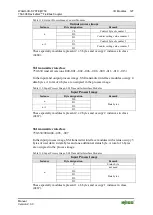
In the input and output process image, data exchange modules occupy 4 data
bytes. 4 bytes are occupied in the process image.
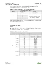
Table 141: Input/Output Process Image, Data Exchange Modules
Input/Output Process Image
Instance
Byte designation
Remark
n
D0
Data bytes
D1
n+1
D2
D3
These specialty modules represent 2 x 2 bytes and occupy 2 instances in class
(0x67) and 2 instances in class (0x68).
WAGO AS-Interface Master
750-655
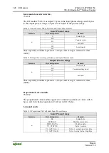
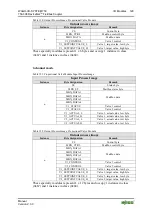
The image process size for the AS-interface master module is adjustable to 12, 24,
32, 40 or 48 bytes. It consists of a control or status byte, a mailbox with 0, 6, 10,
12 or 18 bytes and 0–32 bytes of AS-interface process data. The AS-interface
master module occupies 12–48 bytes in the process image.
The first byte contains the control/status byte, the second contains an empty byte.
Subsequently, mailbox data is mapped when the mailbox is permanently
superimposed (Mode 1). While in operating mode with a suppressible mailbox

