144 I/O Modules
WAGO-I/O-SYSTEM 750
750-306 DeviceNet
TM
Fieldbus Coupler
Manual
Version 2.0.0
11.2.5
System Modules
System Modules with Diagnostics
750-610, -611
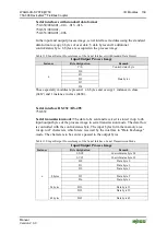
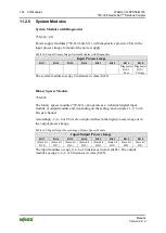
Power supply modules (750-610 and -611) with diagnostics provide 2 bits in the
input process image to monitor the power supply.
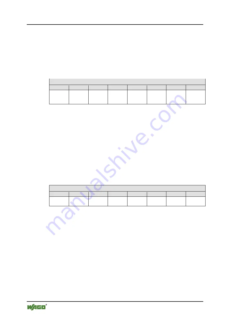
Table 148: Input Process Image, System Modules with Diagnostics
Input Process Image
Bit 7
Bit 6
Bit 5
Bit 4
Bit 3
Bit 2
Bit 1
Bit 0
Diagnostic
bit S 2
Fuse
Diagnostic
bit S 1
Voltage
The system modules occupy 2 instances in class (0x65).
Binary Spacer Module
750-622
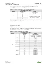
The binary spacer module (750-622) can operate as a 2-channel digital input
module or output module and, depending on the setting, and occupies 1, 2, 3 or 4
bits per channel.
Accordingly, 2, 4, 6 or 8 bits are occupied either in the input process image or in
the output process image.
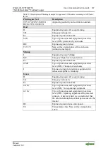
Table 149: Input/Output Process Image, Binary Spacer Module
Input/Output Process Image
Bit 7
Bit 6
Bit 5
Bit 4
Bit 3
Bit 2
Bit 1
Bit 0
(Data bit
DI 8)
(Data bit
DI 7)
(Data bit
DI 6)
(Data bit
DI 5)
(Data bit
DI 4)
(Data bit
DI 3)
Data bit
DI 2
Data bit
DI 1
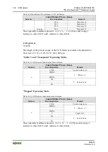
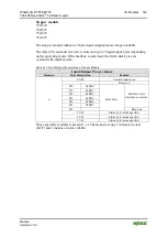
The input modules occupy 2, 4, 6 or 8 instances in class (0x65). The output
modules occupy 2, 4, 6 or 8 instances in class (0x65).

