160 List of Tables
WAGO-I/O-SYSTEM 750
750-306 DeviceNet
TM
Fieldbus Coupler
Manual
Version 2.0.0
List of Tables
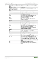
Table 3: Legend for Figure “System Supply via Fieldbus Coupler/Controller (left)
and via Internal System Supply Module (right)” ......................................... 20
Table 5: Legend for Figure “Field Supply for Standard Couplers/Controllers and
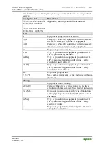
Table 8: Legend for Figure “Supply Example for Fieldbus Coupler/Controller” . 31
Table 9: WAGO Power Supply Units (Selection) ................................................. 32
Table 10: WAGO Ground Wire Terminals ........................................................... 33
Table 11: Legend for Figure “View DeviceNet
Fieldbus Coupler” .................. 39
Table 12: Pin Assignment for the Fieldbus Connection, Series 231
Table 16: Legend for Figure “Service Interface (Closed and Opened Flap)” ....... 43
Table 17: Setting the Baud Rate via DIP Switch .................................................. 44
Table 20: Technical Data, DeviceNet
fieldbus .................................................. 46
Table 24: Technical Data – Power Jumper Contacts ............................................ 47
Table 26: Technical Data – Climatic Environmental Conditions ......................... 48
Table 27: Technical Data – Mechanical Strength acc. to IEC 61131-2 ................ 48
Table 34: Node Status Diagnostics – Solution in Event of Error .......................... 76
Table 35: Blink code- table for the I/O LED signaling, error code 1 .................... 78
Table 36: Blink Code Table for the I/O LED Signaling, Error Code 2 ................ 79
Table 37: Blink Code Table for the I/O LED Signaling, Error Code 3 ................ 80
Table 38: Blink Code Table for the I/O LED Signaling, Error Code 4 ................ 81
Table 39: Blink Code Table for the I/O LED Signaling, Error Code 5 ................ 81
Table 40: Blink Ccode Table for the I/O LED Signaling, Error Code 6 … 8 ....... 82
Table 41: Blink Code Table for the I/O LED Signaling, Error Code 9 ................ 82
Table 42: Blink code table for I/O LED signaling, error code 10 ......................... 82
Table 43: Blink Code Table for the I/O LED Signaling, Error Code 11 .............. 83
Table 44: Power Supply Status Diagnostics – Solution in Event of Error ............ 83
Table 45: Maximum bus lengths dependent on preset baud rate .......................... 86
Tap Versions ................................................................... 89


