162 List of Tables
WAGO-I/O-SYSTEM 750
750-306 DeviceNet
TM
Fieldbus Coupler
Manual
Version 2.0.0
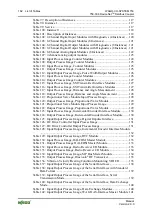
Table 102: 2-Channel Digital Input Modules with Diagnostics (4 Instances) .... 120
Table 103: 8-Channel Digital Input Modules (8 Instances) ................................ 121
Table 104: 8-Channel Digital Output Modules with Diagnostics (8 Instances) . 121
Table 105: 8-Channel Digital Output Modules with Diagnostics (8 Instances) . 121
Table 106: 8-Channel Analog Input Modules (8 Instances) ............................... 122
Table 108: Input Process Image Counter Modules ............................................. 124
Table 109: Output Process Image Counter Modules ........................................... 125
Table 110: Input Process Image, Counter Modules ............................................ 125
Table 111: Output Process Image, Counter Modules .......................................... 125
Table 112: Input/Output Process Image, Pulse Width Output Modules ............. 126
Table 113: Input Process Image Counter Modules ............................................. 126
Table 114: Output Process Image Counter Modules ........................................... 127
Table 115: Input Process Image, SSI Transmitter Interface Modules ................ 127
Table 116: Input Process Image, SSI Transmitter Interface Modules ................ 127
Table 117: Input Process Image, Distance and Angle Measurement .................. 128
Table 118: Output Process Image, Distance and Angle Measurement ............... 128
Table 119: Proportional Valve Module Input Process Image ............................. 128
Table 120: Output Process Image, Proportional Valve Module ......................... 129
Table 121: Proportional Valve Module Input Process Image ............................. 129
Table 122: Output Process Image, Proportional Valve Module ......................... 129
Table 123: Input Process Image, Incremental Encoder Interface Module .......... 130
Table 124: Output Process Image, Incremental Encoder Interface Module ....... 130
Table 125: Input/Output Process Image, Digital Impulse Interface .................... 131
Table 126: DC Drive Controller Input Process Image ........................................ 131
Table 127: DC Drive Controller Output Process Image ..................................... 131
Table 128: Input/Output Process Image, Incremental Encoder Interface Module
Table 129: Input/Output Process Image, RTC Module ....................................... 132
Table 130: Input Process Image, DALI/DSI Master Module ............................. 133
Table 131: Output Process Image DALI/DSI Master Module ............................ 133
Table 132: Input Process Image, Radio Receiver I/O Module ............................ 133
Table 133: Output Process Image, Radio Receiver I/O Module ......................... 134
Table 134: Input/Output Process Image, MP Bus Master Module ..................... 134
Table 135: Output Process Image,
RF Transceiver .......................... 135
Table 136: Vibration Velocity/Bearing Condition Monitoring VIB I/O ............ 135
Table 137: Input/Output Process Image of the Serial Interfaces ......................... 138
Table 138: Input/Output Process Image of the Serial Interfaces with Standard
Table 139: Input/Output Process Image of the Serial Interface, Serial
Table 140: Input/Output Process Image of the Serial Interface, Data Exchange
Table 141: Input/Output Process Image, Data Exchange Modules ..................... 140
Table 142: Input/Output Process Image, WAGO AS-Interface Master Module 141

