WAGO-I/O-SYSTEM 750
Device Description
39
750-306 DeviceNet
TM
Fieldbus Coupler
Manual
Version 2.0.0
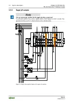
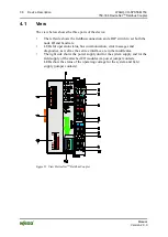
Table 11: Legend for Figure “View DeviceNet
TM
Fieldbus Coupler”
Pos.
Desig-
nation
Meaning
Details see Section
1
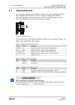
OVERFL,
RUN,
BUS OFF,
CONNECT
Status LEDs Fieldbus
“Device Description” >
“Display Elements”
2
---
Group marking carrier (retractable) with
additional marking possibility on two miniature
WSB markers
---
3
A, B or C Status LED’s System/Field Supply
“Device Description” >
“Display Elements”
4
---
Data Contacts
“Connect Devices” > “Data
Contacts/Internal Bus”
5
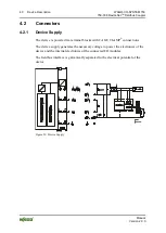
24 V, 0 V CAGE CLAMP
®
Connections System Supply
“Connect Devices” >
“Connecting a conductor to
the CAGE CLAMP
®
”
6
+
CAGE CLAMP
®
Connections Field Supply
24 VDC
“Connect Devices” >
“Connecting a conductor to
the CAGE CLAMP
®
”
7
---
Power Jumper Contact 24 VDC
“Connect Devices” >
“Power Contacts/
Field Supply”
8
---
Unlocking Lug
“Mounting” >
“Inserting and Removing
Devices”
9
-
CAGE CLAMP
®
Connections Field Supply 0 V
“Connect Devices” >
“Connecting a conductor to
the CAGE CLAMP
®
”
10
---
Power Jumper Contact 0 V
“Connect Devices” >
“Power Contacts/
Field Supply”
11
(Ground)
CAGE CLAMP
®
Connections Field Supply
(Ground)
“Connect Devices” >
“Connecting a conductor to
the CAGE CLAMP
®
”
12
---
Power Jumper Contact (Ground)
“Connect Devices” >
“Power Contacts/
Field Supply”
13
---
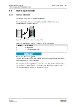
Service Interface (open flap)
“Device Description” >
“Operating Elements”
16
---
DIP Switch
“Device Description” >
“Operating Elements”
15
---
Locking Disc
“Mounting” > “Inserting
and Removing Devices”
16
---
Fieldbus Data contacts connection, 231 Series
(MCS)
“Device Description“ >
“Connectors“

