WAGO-I/O-SYSTEM 750
Function Description
65
750-306 DeviceNet
TM
Fieldbus Coupler
Manual
Version 2.0.0
7.2
Process Data Architecture
7.2.1
Basic Setup
After switching on the fieldbus coupler, it identifies all I/O modules of the node
that send or expect to receive data (data/bit width > 0). Any number of analog
input/output modules and digital input/output modules can be arranged within a
node.
Additional Information
For the number of input and output bits or bytes of the individual I/O modules,
refer to the corresponding description of the I/O modules.
The coupler creates an internal local process image on the basis of the data width,
the type of I/O module and the position of the module in the node. This process
image is separated into input and output data range.
The data of the digital input/output modules is bit-oriented, i.e., data is exchanged
bit by bit. The analog I/O bus modules represent all byte-oriented bus modules,
which send data byte by byte.
This group includes: counter modules, angle and distance measurement modules
and communication modules.
For both, the local input and output process image, the I/O module data is stored
in the corresponding process image depending on the order in which the modules
are connected to the coupler.
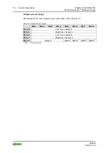
First, all the byte-oriented (analog) IO modules are filed in the process image,
then the bit-oriented (digital) IO modules. The bits of the digital modules are
grouped into bytes. If the amount of digital information exceeds 8 bits, the coupler
automatically starts with a new byte.
Hardware changes can result in changes of the process image!
If the hardware configuration is changed by adding, changing or removing of I/O
modules with a data width > 0 bit, this result in a new process image structure.
The process data addresses would then change. If adding I/O modules, the process
data of all previous I/O modules has to be taken into account.

