72
Commissioning
WAGO-I/O-SYSTEM 750
750-306 DeviceNet
TM
Fieldbus Coupler
Manual
Version 2.0.0
8.1
Connecting Client PC and Fieldbus Nodes
1.
Mount the fieldbus node to the carrier rail.
Observe the installation instructions described in “Mounting” section.
2.
Use a fieldbus cable to connect the DeviceNet
TM
fieldbus node to the
DeviceNet
TM
fieldbus card in your PC.
24V power is supplied to the fieldbus via connections V+, V- of the 5-pin
fieldbus connector (Series 231
(MCS)
) from an external fieldbus power supply
unit.
3.
Turn the operating voltage on.
4.
Turn on your PC.
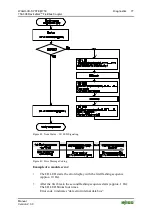
The fieldbus coupler is initialized. The coupler determines the I/O module
configuration and creates a process image.
During start-up, the I/O LED (red) flashes.
If the I/O LED lights up green after a brief period, the fieldbus coupler is
operational.
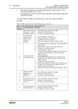
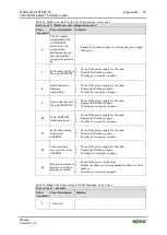
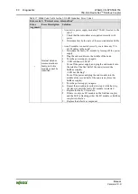
If an error occurs during start-up indicated by the I/O LED flashing red, evaluate
the error code and argument and resolve the error.
More information about LED signaling
The exact description for evaluating the LED signal displayed is available in the
section “Diagnostics” > … > “LED Signaling”.

