76
Diagnostics
WAGO-I/O-SYSTEM 750
750-306 DeviceNet
TM
Fieldbus Coupler
Manual
Version 2.0.0
9.1.2
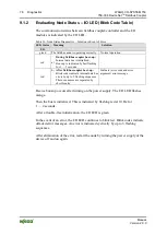
Evaluating Node Status – I/O LED (Blink Code Table)
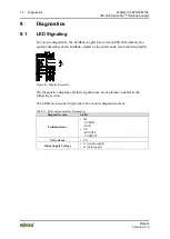
The communication status between fieldbus coupler/controller and the I/O
modules is indicated by the I/O LED.
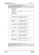
Table 34: Node Status Diagnostics – Solution in Event of Error
LED Status
Meaning
Solution
I/O
green
The fieldbus node is operating correctly.
Normal operation.
red
a.)
During fieldbus coupler boot-up:
Internal data bus is initialized,
Boot-up is indicated by fast flashing
for 1 … 2 seconds.
-
red
b.)
After fieldbus coupler boot-up:
Blink codes indicate internal data bus
errors by up to 3 flashing sequences.
These sequences are separated by
short breaks.
Evaluate (error code and error
argument) error message
Device boot-up occurs after turning on the power supply. The I/O LED flashes
orange.
Then the bus is initialized. This is indicated by flashing red at 10 Hz for
1 … 2 seconds.
After a trouble-free initialization, the I/O LED is green.
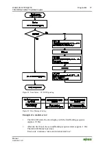
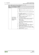
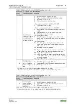
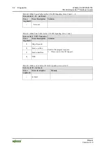
In the event of an error, the I/O LED continues to blink red. Blink codes indicate
detailed error messages. An error is indicated cyclically by up to 3 flashing
sequences.
After elimination of the error, restart the node by turning the power supply of the
device off and on again.


