WAGO-I/O-SYSTEM 750
Diagnostics
79
750-306 DeviceNet
TM
Fieldbus Coupler
Manual
Version 2.0.0
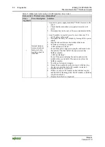
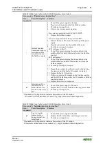
Table 35: Blink code- table for the I/O LED signaling, error code 1
Error code 1: “Hardware and configuration error”
Error
Argument
Error Description
Solution
6
The I/O module
configuration after
AUTORESET
differs from the
configuration
determined the last
time the fieldbus
coupler was powered
up.
1. Restart the fieldbus coupler by turning the power supply
off and on.
7
Fault when writing in
the serial EEPROM.
1. Turn off the power supply for the node.
2. Replace the fieldbus coupler.
3. Turn the power supply on again.
8
Invalid hardware-
firmware
combination.
1. Turn off the power supply for the node.
2. Replace the fieldbus coupler.
3. Turn the power supply on again.
9
Invalid check sum in
the serial EEPROM.
1. Turn off the power supply for the node.
2. Replace the fieldbus coupler.
3. Turn the power supply on again.
10
Serial EEPROM
initialization error
1. Turn off the power supply for the node.
2. Replace the fieldbus coupler.
3. Turn the power supply on again.
11
Fault when reading
in the serial
EEPROM.
1. Turn off the power supply for the node.
2. Replace the fieldbus coupler.
3. Turn the power supply on again.
12
Timeout during
access on the serial
EEPROM
1. Turn off the power supply for the node.
2. Replace the fieldbus coupler.
3. Turn the power supply on again.
14
Maximum number of
gateway or mailbox
modules exceeded
1. Turn off the power for the node.
2. Reduce the number of corresponding modules to a valid
number.
3. Turn the power supply on again.
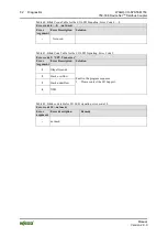
Table 36: Blink Code Table for the I/O LED Signaling, Error Code 2
Error code 2: – not used –
Error
Argument
Error Description
Solution
1
Not used
-

