WAGO-I/O-SYSTEM 750
Function Description
69
750-306 DeviceNet
TM
Fieldbus Coupler
Manual
Version 2.0.0
Take into account the process data of previous I/O modules in case of an
expansion!
If a node is changed or expanded, this may result in a new process image
structure. In this case, the process data addresses also change. In case of an
expansion, the process data of all previous I/O modules has to be taken into
account.
Example of a static assembly:
On delivery of the fieldbus coupler, the default setting for the static assembly is:
•
Output1 (I/O Assembly Instance 1)
•
Input1 (I/O Assembly Instance 4)
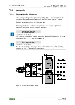
Example setup of the fieldbus node:
1.
DeviceNet
TM
fieldbus coupler (750-306)
2.
4-channel digital input module (e.g., 750-402)
3.
4-channel digital output module (e.g., 750-504)
4.
2-channel analog output module with 2 bytes per channel (e.g., 750-552)
5.
2-channel analog input module with 2 bytes per channel (e.g., 750-456)
6.
End module (750-600)
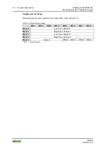
Input process image:
Standard process data, input image (Assembly Class, Instance 4)
Table 29: Input Process Image
Bit 7
Bit 6
Bit 5
Bit 4
Bit 3
Bit 2
Bit 1
Bit 0
Byte 0
Low byte channel 1
Byte 1
High byte channel 1
Byte 2
Low byte channel 2
Byte 3
High byte channel 2
Byte 4
unused
DI04
1)
DI03
1)
DI02
1)
DI01
1)
Byte 5
DS08
2)
DS07
2)
DS06
2)
DS05
2)
DS04
2)
DS03
2)
DS02
2)
DS01
2)
1)
DI = Digital input
2)
DS =
Diagnostic status (The last byte in the input process image is the diagnostic status byte,
DS01 … DS08, see also object 0x64/Instance 1/Attr. 5.)
DS01 =1: Internal bus error (0x01)
DS02 =1: Coupler configuration error (0x02)
DS04 =1: Module diagnostics (0x08)
DS08 =1: Fieldbus error (0x80)

