WAGO-I/O-SYSTEM 750
Diagnostics
83
750-306 DeviceNet
TM
Fieldbus Coupler
Manual
Version 2.0.0
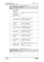
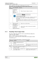
Table 43: Blink Code Table for the I/O LED Signaling, Error Code 11
Error code 11: “Error in I/O modules with gateway/mailbox functionality”
Error
Argument
Error Description
Remedy
1
Too many I/O
modules with
gateway
functionality are
plugged in
1. Reduce the number of gateway modules.
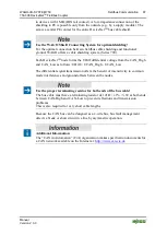
Note process image size limit!
Please note the process image size limit when configuring a node with
analog input/output modules and I/O modules that have mailbox
functionality.
Depending on the overall configuration of all I/O modules of a node, the
maximum number of object directory entries may be exceeded in some
cases.
2
Maximum mailbox
size exceeded
1. Reduce the size of the mailbox.
3
Maximum PA size
exceeded due to
connected I/O
modules with
mailbox functionality
1. Reduce the data width of I/O modules with mailbox
functionality.
9.1.3
Evaluating Power Supply Status
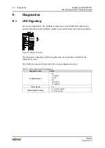
The power supply unit of the device has two green LEDs that indicate the
status of the power supplies.
LED “A” indicates the 24 V supply of the coupler.
LED “B” or “C” reports the power available on the power jumper contacts
for field side power.
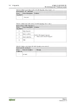
Table 44: Power Supply Status Diagnostics – Solution in Event of Error
LED Status Meaning
Solution
A
Green
Operating voltage for the system is
available.
-
Off
No power is available for the system
Check the power supply for the system
(24 V and 0 V).
B or C
Green
The operating voltage for power jumper
contacts is available.
-
Off
No operating voltage is available for the
power jumper contacts.
Check the power supply for the power
jumper contacts (24 V and 0 V).


