8 •
750-635 [Digital Impulse Interface]
Schematic Diagram
WAGO-I/O-SYSTEM
750
I/O
Modules
Attention
This module has no power contacts for ground (earth). For field supply with
ground (earth) to downstream I/O modules, a supply module will be needed.
The module can be used with all couplers/controllers of the
WAGO-I/O-SYSTEM 750 (except for the economy types 750-320, -323, -324
and -327).
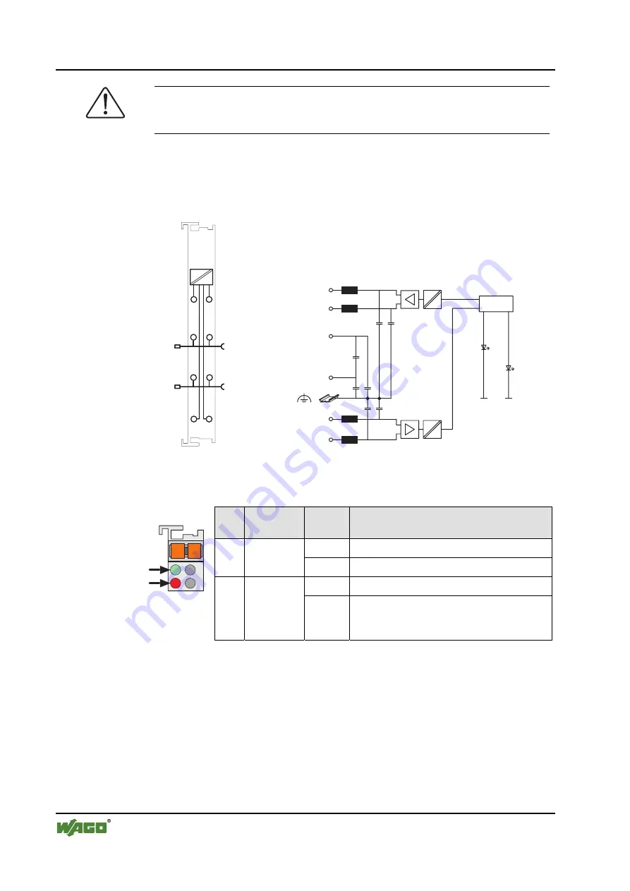
2.1.1.3 Schematic
Diagram
I
I
S
S
_
_
_
_
I
24V
0V
S
I
Function
24V
0V
Logic
Error
S
2 x 10nF
1 x 10nF
2 x 270pF
2 x 270pF
1
2
3
4
5
6
7
8
750-635
Fig. 2.1.1-2: 1 Channel Digital Impulse Interface 750-635
g063501e
2.1.1.4 Display
Elements
LED Designa-
tion
Status Function
off
Module is not taking part in data exchange
A
green
Function
on
Module is taking part in data exchange
off Faultless
operation
13 14
C
D
B
A
A
B
Fig. 2.1.1-3: Dis-
play Elements
g063802x
B
red
Error
on
Line break
No acknowledgement from sensor,
waveguide velocity is not set


