234 • I/O modules
Incremental-encoder interface 750-631
Modular I/O System
ETHERNET TCP/IP
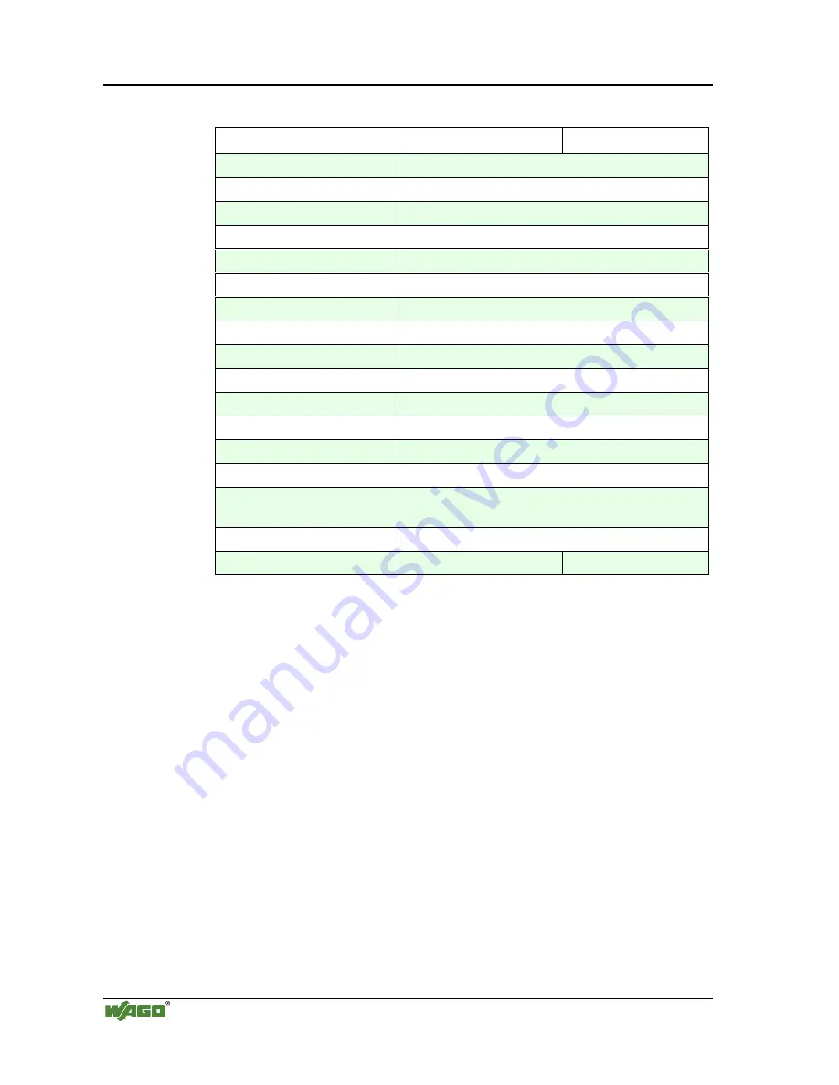
Technical Data:
Item-No.:
750-631
750-631/000-001
Encoder connections
A, A (inv), B, B (inv), C, C (inv)
current consumption (internal)
25 mA
Sensor supply Voltage
DC 5 V
Data word
16 Bit Binary
Maximum Frequency
1 MHz
Quadraturdecoder
1-2-4 times sampling
Data Latch word
16 Bit
Commands
read, reset, start
Supply Voltage
DC 24 V (- 15 % / + 20 %)
Input current (internal)
85 mA typ. without sensor
Sensor output current
300 mA max.
Internal bit width
1 x 32 Bit Data, 1 x 8 Bit control/status
Configuration
none, or via software with the consent of WAGO
Operating temperature
0 °C ... + 55 °C
Wire connection
CAGE CLAMP
; 0.08 mm
2
- 2.5 mm
2
, AWG 28 – 14,
8 – 9 mm Stripped length
Dimensions (mm) WxHxL
24 x 64* x 100 (*from upper edge of carrier rail)
Default configuration
4 times sampling
1 times sampling
Operational Characteristics:
The quadrature encoder interface accepts up to two input signals for the coun-
ting increment. The index pulse may also be considered should the control
configuration require it. There is also a Latch and Gate input available on the
module for added functionality.
The quadrature encoder provides two signals that are shifted 90 degrees from
each other, signals A and B. In order to achieve a better common mode noise
rejection ratio, the output signals from the encoder are transmitted via a diffe-
rential signal. Their complement signals, A(inv.) and B(inv.) are also trans-
mitted. A directional determination may be made by which signal leads. If the
A signal leads, the direction is considered to be forward. If the B signal leads,
the direction is considered to be reverse.
By exchanging the A and A(inv.) the phase relationship will be changed by
180 degrees, thus allowing the direction to be preset via the wiring configura-
tion.


