background image

8


Plotter IP350

IMPORTANT:


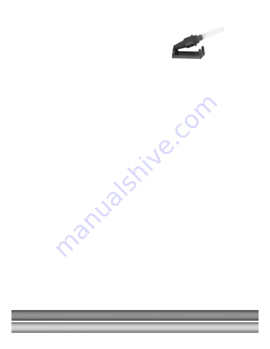
Only plotter pens of the type shown here may be 
Used, as the sealing system is designed for these  
plotter pens specifially. Using other plotter pens and 
writing instruments can damage the device. 


To insert plotter pens into the pen station, press the 'Pen station OPEN/CLOSE' key. This is 
only possible when the system is in stop mode. When the pen station has been 
opened you can insert the plotter pens into the corresponding storage holders and then re-
close the pen station by pressing the OPEN/CLOSE key again. 
 

PLEASE


NOTE 

Do not leave the pen station open for extended periods as there is a danger the pens will 
dry out. You can leave plotter pens in the pen station because the optimized seal 

largely prevents pens from drying out. If the storage holders become soiled over time you 
can replace them. The product codes for storage holders and the procedure for 
changing them can be found in the chapter Accessories.  
 

4. Stop/view-key 

If the 'stop/view' key is activated while the plotter is in action, the job will immediately pause 
and the plotter pen will move into the top right-hand corner after the pen 
has been deposited. The red light will signal the interruption. Pressing the key again will 
calibrate the writing arm and the plotter will continue with the job. The red lamp will turn off. 
 

ATTENTION: 

Inserting a pen into the writing arm holder by hand can involve inadvertently moving the 
writing arm and compromising the calibration. After inserting the pen, press the 'stop/view' 
key twice to recalibrate the system. 
 

5.  Cursor-keys / Pen up/down key


These keys can be used to move the writing arm manually in all directions. The 'pen 
up/down' key lowers and raises the plotter pen. The system must be in stop mode. 
 

PLEASE NOTE: 

These key functions are not used for normal operation. They are intended solely for the 
adjustment settings and servicing. 
 

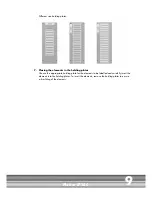
6.  Placing the holder plates in the WAGO Plotter 


There are eight pin stops on the plotting area where up to four different holder plates can be 
loaded. Different fixtures are available depending on the size of the marking elements. They 
may occupy one, two or four segments on the plotting area. 


PLEASE NOTE: 

When fitting fixtures or inserting marking elements into the fixtures it is possible for the writing 
arm to be moved out of place, altering the calibration. If the writing arm is moved, press the 
'stop/view' key twice to recalibrate the system. 


Summary of Contents for IP 350

Page 1: ...Manual Plotter IP 350...

Page 2: ...upply 4 3 Product overview 5 4 Setting up the Vario Plotter IP 350 6 4 1 Location 6 4 2 Connections 6 5 Operation 7 6 Cleaning and product care 10 7 Accessories 11 8 Troubleshooting 13 9 Technical Inf...

Page 3: ...r pen seal The pens can be stored in the plotter s pen station Auto calibration no adjustment necessary Capable of labelling marking elements up to 10 5 mm in height Special solutions for up to 15 mm...

Page 4: ...ee list below Please retain the packaging in case you need to return the device The following items are supplied as standard 1 WAGO Plotter IP 350 2 Power supply with corresponding mains power cable 3...

Page 5: ...rea 5 Pin stops for holding plates 6 Vacuum supply of the individual segments 7 Penholder pen receptacle 8 Lowering unit 9 Vacuum connection point 10 Mains connection 11 Gate terminal for external dev...

Page 6: ...ove freely and is not obstructed by other objects 4 2 Connections Plug the device into a correctly installed mains socket using the power supply included with the product The power supply features a v...

Page 7: ...to activate and deactivate the device When the plotter is switched on the writing arm moves to the top right hand corner of the labelling area and auto calibration takes place The green indicating lig...

Page 8: ...nd corner after the pen has been deposited The red light will signal the interruption Pressing the key again will calibrate the writing arm and the plotter will continue with the job The red lamp will...

Page 9: ...g the elements in the holding plates Choose the appropriate holding plate for the elements to be labelled and carefully insert the elements into the holding plates To insert the elements remove the ho...

Page 10: ...ver is supplied as accessory Wipe the device occasionally after use with a dry lint free cloth or a mild cleaning agent If the pen station storage holders are heavily soiled please replace them IMPORT...

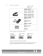
Page 11: ...O ink cartridges 258 141 WAGO service kit 258 147 Dust cover 258 146 EXCHANGING SEALING UNIT IN THE PEN STATION REMOVING A SEALING UNIT FROM THE PEN STATION First open the pen station by pressing the...

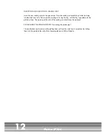
Page 12: ...adjust the sealing unit using the key until the key is parallel with the plotter surface The opening at the side of the sealing unit should now be centered EXCHANGING THE PRIMING PLATES for starting t...

Page 13: ...s not respond to data downloaded from PC Is the interface cable connected properly Replace the data cable if necessary Is the correct interface on the PC being used No labelling is taking place even t...

Page 14: ...eat accuracy after pen change 0 05 mm with optimum pen Power supply Separate power supply with exchangeable mains power connection Power supply input voltage Power supply input current 100 240V AC 50...

Page 15: ...ds and all applicable safety regulations The mains power supply used must correspond with that specified on the name plate Use in dry conditions only Disconnect the device from the mains socket by pul...

Page 16: ...a e 27 D 32423 Minden Phone 49 571 887 0 Fax 49 571 887 169 info wago com www wago com Support Hotline ProServe Phone 49 571 887 630 Fax 49 571 887 8630 support proserve wago com 0888 0415 0300 3601 M...

Reviews: