38 Properties
Touch Panel Marine Line
762-6xxx/8000-000x TP 600
Manual
Version 1.1.0
4.6
Display Elements
4.6.1
Status LED
There is a three-color status LED on the front for displaying operating and error
messages.
The indicators are explained as follows:
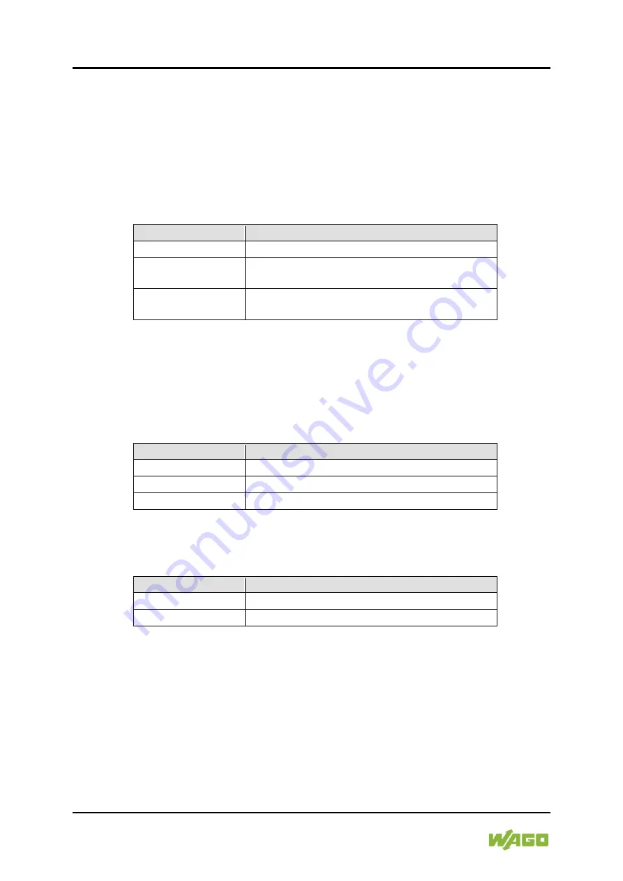
Table 12: Status LED
LED Display
Explanation
Green, steady
The panel is ready to operate.
Red, flashing
There is an error.
The specific error message is displayed.
Blue, flashing
There is a connection error to the controller. No
communication
One three-color LED and four two-color LEDs are located on the left side. The
meaning of the three-color SYS LED is analogous to that of the status LED on
the front.
The RUN LED indicates the program status.
Table 13: RUN LED
LED Display
Explanation
Green flashing
No application and no boot project loaded.
Green, steady
e!
RUNTIME
applications running.
Red, steady
All
e!
RUNTIME
applications have stopped.
The CAN LED indicates the CANopen status.
Table 14: CAN LED
LED Display
Explanation
Green, steady
CAN communication is running.
Red, steady
CAN communication is disrupted.
Two other user LEDs, “H11” and “H22,” are provided for future applications.
4.6.2
Feedback LEDs for the Brightness Buttons
Two capacitive buttons with visual feedback from two white LEDs are used to set
the display brightness.


