WAGO-I/O-SYSTEM 750
Device Description
27
750-657 IO-Link Master
Manual
Version 1.0.2, valid from FW/HW-Version 02/01
4.5.4
IO-Link Ports
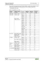
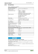
Table 11: Technical Data – IO-Link Ports
Operation mode IO-Link
IO-Link specification
v1.0, v1.1 acc.to IEC 61131-9
Number of ports
4
Communication mode
COM1 ( 4,8 kBaud)
COM2 ( 38,4 kBaud)
COM3 (230,4 kBaud)
Depending on connected sensor/actuator
Operation modes
IO-Link/SIO (Standard Input/Output)
DI (Digital Input, Default)
DO (Digital Output)
Inactive
Frame types
0, 1.1-1.2, 1.V, 2.1-2.6, 2.V
Connection type
Unshielded standard 3-wire cable
(Physics 2 acc. IO-Link standard)
Line length
max.
20
m
Sensor supply U
V
DC 24 V
Nominal current per port (L+) 200 mA
Maximum current per port
(C/Q)
100 mA
Short-circuit-protected (C/Q)
yes
Short-circuit current
max.
(C/Q) 450 mA
Operation mode SIO/DI (Input type 1 acc. to norm EN 61131-2:2007)
Signal current (0)
6 mA typ.
Signal voltage (0)
5 V
Signal current (1)
7 mA typ.
Signal voltage (1)
15 V
Operation mode DO
Output voltage
DC 24 V
Output current
max.
100
mA
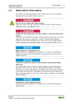
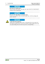
Note reverse polarity protection and connection!
The supply of 24 V to the power contacts is protected against reverse polarity if
the potential on C/Q is not 0 V!
Simultaneous reverse polarity and short circuit on C/Q against 0 V can cause
destruction!
Incorrectly connecting a device to the L+/L- connection of the IO-Link master can
destroy the device.
Ensure that the connection is correct.

