WAGO-I/O-SYSTEM 750
Function Description
31
750-657 IO-Link Master
Manual
Version 1.0.2, valid from FW/HW-Version 02/01
Pos: 66 /Alle Serien (Allgemeine Module)/Überschriften für alle Serien/Funktionsbeschreibung - Überschrift 1 @ 4\mod_1239025975389_21.doc @ 30003 @ 1 @ 1
5 Function
Description
Pos: 67 /Serie 750 (WAGO-I/O-SYSTEM)/Funktionsbeschreibung/Funktionsbeschreibung 750-657 @ 10\mod_1301902292811_21.doc @ 71500 @ 2 @ 1
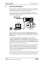
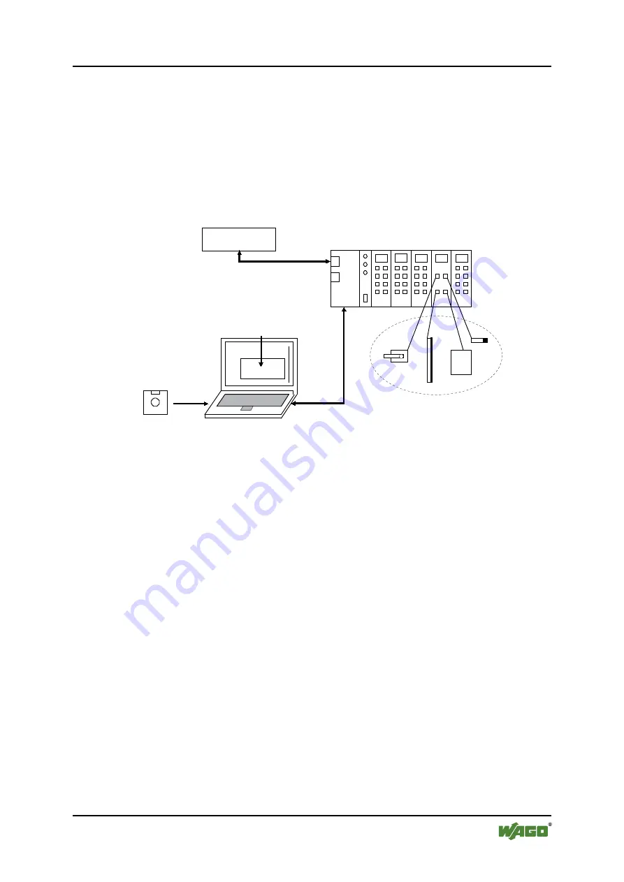
The IO-Link master is operated on a fieldbus coupler/controller of the WAGO-
I/O-SYSTEM 750. Up to four IO-Link devices according to IEC 61131-9 or four
digital inputs/outputs can be connected to the IO-Link master.
Device description files are used to configure and parameterize the IO-Link
master and IO-Link devices via the WAGO-I/O-
CHECK
software (see section
"Configuration and Parameterization").
RFID
Limit switches
IO-Link devices
or
current digital inputs/outputs
Light barriers
BERO
Parameterization
and configuration
of IO-Link master
and IO-Link devices
IODD for
IO-Link devices
Fieldbus
Fieldbus coupler
IO-Link
master
Higher level control
Figure 9: Complete system
The IO-Link master supports 4 operating modes:
IO-Link
or
SIO
("Standard
Input/Output"),
DI
("Digital Input", default setting),
DO
("Digital Output") and
Inactive
. The respective operating mode can be set separately for each port of the
IO-Link master.
The data between the IO-Link master and attached devices is exchanged
cyclically via the
IO-Link
interface and depending on the source, processed
accordingly and transferred via the
internal bus
. Process input data is transferred
via the fieldbus to the control or process output data via the
fieldbus
and internal
bus to the I/O module. Details on the use of certain fieldbuses is available in the
appendix, section "Fieldbus-Specific Additions".
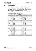
The process image of the IO-Link master can be set to up to 24 bytes depending
on the device attached. The process image is divided into control/state byte,
Mailbox bytes, SIO byte and an area divided into 4 segments used for the 4 IO-
Link ports. If the set segment size of a port is insufficient to transfer the data in
one cycle, the data of the individual IO-Link devices can also be transferred
fragmented via the respective port.
Parameters and data from the IO-Link master and attached IO-Link devices can be
accessed from the PLC via the process image. In this way, any parameterization
processes and backup procedures can be carried out from the PLC at run-time.

