56
Configuration and Parameterization
WAGO-I/O-SYSTEM 750
750-657 IO-Link Master
Manual
Version 1.0.2, valid from FW/HW-Version 02/01
Data Direction Control
I/O Module
Table 24: Register “Master Configuration”
Option
Description
Output (Downstream)
Offset Port x
Position of a port segment in relation to the control/status byte
Length Port x
Set the length of a port segment in bytes.
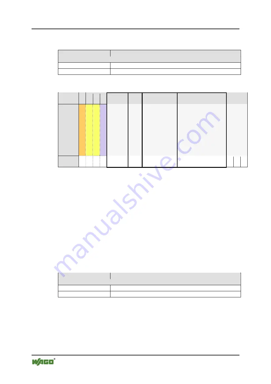
Table 25: Internal bus process data, Example of a segment distribution with a 2-byte Mailbox size
Byte /
Offset
0 1 2 3
Offset
= 4
Offset
= 7
Offset
= 9
Offset
= 14
21 22 23
Content
C
ont
ro
l byt
e
/ st
at
us
by
te
M
ailbo
x / Reg
.ister co
mm.
M
ailbo
x / Reg
ister comm.
SIO byte
Segme
nt
P
ort
1
Segme
nt
P
ort
1
Segme
nt
P
ort
1
Segme
nt
P
ort
2
Segme
nt
P
ort
2
Segme
nt
P
ort
3
Segme
nt
P
ort
3
Segme
nt
P
ort
3
Segme
nt
P
ort
3
Segme
nt
P
ort
3
Segme
nt
P
ort
4
Segme
nt
P
ort
4
Segme
nt
P
ort
4
Segme
nt
P
ort
4
Segme
nt
P
ort
4
Segme
nt
P
ort
4
Segme
nt
P
ort
4
Un
use
d, 0
x00
Un
use
d, 0
x00
Un
use
d, 0
x00
Segment
length
Size
= 3
Size
= 2
Size
= 5
Size
= 7
A few rules must be followed during segmentation:
•
The smallest value for Offset is 4.
The first 4 bytes of the internal bus process image are already occupied by
the status/control byte, at least two Mailbox bytes and the SIO byte.
•
Segments may not overlap
Segments can only lie next to each other.
•
Offset
+
port segment length must lie within the internal bus
The width of the internal bus process image must be configurable within 4,
6, 8, 10, 12, 16, 20 and 24 bytes.
Data Direction I/O Module
Control
Table 26: Register “PI Segmentation”
Option
Description
Input (Upstream)
Offset Port x
Position of a port segment in relation to the control/status byte
Length Port x
Set the length of a port segment in bytes.

