WAGO-I/O-SYSTEM 750
Configuration and Parameterization
59
750-657 IO-Link Master
Manual
Version 1.0.2, valid from FW/HW-Version 02/01
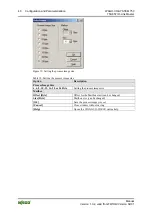
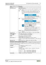
Table 27: Register “Port Configuration”
Option
Description
Operation Mode
Select operating mode:
IO-Link
Operating mode for connecting an IO-Link-enabled device to
a port
DI
Port functions at a type 1 input according to IEC 61131-2.
The input is cyclically queried by the IO-Link master. The
data is transferred via the internal bus to the higher level
control.
Ensure that the sensor is connected properly!
The I/O module can be destroyed if the sensor is not
connected properly in "DI" mode.
DO
The port behaves like a standard digital output. The
maximum output current is 100 mA.
Ensure that the actuator is connected properly!
The I/O module can be destroyed if the actuator is
not connected properly in "DO" mode.
I/O module can be destroyed!
A short circuit or over-current (> 250 mA) causes
the output to switch off. The I/O module
automatically attempts to activate the output again.
If unsuccessful, the output remains off.
Inactive
The port is disabled and ignored by the internal device
software.
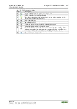
Transfer rate
Display of the transfer rate and COM port, e.g. 38.4 kbit/s (COM2)
Enable port diagnosis via the Mailbox
Enable diagnosis
over mailbox
Disable port diagnosis via the Mailbox
IODD
Select the device description file IODD
(the
[Connect]
button may not be active)
[Show Device…]
Display IODD of the attached device in the new window
(can only be selected with IO-Link-enabled devices), see the following
section.
[Refresh List]
Refresh the list if new IODD has been added to the folder.
Maximum cycle time for polling of IO-Link devices
The master cycle time describes the minimum cycle time, in which the IO-Link master queries the
attached IO-Link devices. Set for multiplier and timebase values. The resulting cycle time appears
as the result of the term directly.
Multiplier
Set multiplier for the master cycle time
(“0” = FreeRunning)
Set timebase
Depending on the "Timebase" value set, calculation of the master
cycle time changes:
Timebase
0,1 ms
0,4 ms
1,6 ms
0,0 ms + MULTIPLIER * TIMEBASE
6,4 ms + MULTIPLIER * TIMEBASE
32,0 ms + MULTIPLIER * TIMEBASE
Actual value
Displays the current value in milliseconds.

