126 Appendix
WAGO-I/O-SYSTEM
750
750-657 IO-Link Master
Manual
Version 1.0.2, valid from FW/HW-Version 02/01
11.4.1
PROFIBUS
If you use the IO-Link master on a PROFIBUS coupler, the process image is 2
bytes shorter. The acyclic channel of the I/O module does not appear in the cyclic
process image.
Connect max. 16 I/O modules to PROFIBUS couplers!
When using a PROFIBUS fieldbus coupler, max. 16 I/O modules can be operated
with an acyclic channel (Mailbox 2.0).
11.4.1.1 Process Image
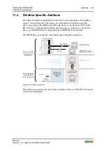
The structure of the process image for PROFIBUS is defined as follows:
Control/Status
byte
SIO byte
Port 1
Port 2
Port 3
Port 4
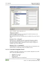
Figure 43: Process image
11.4.1.2 Configuring with PROFIBUS GSD/GSE
If the I/O module is operated on a PROFIBUS coupler, the IO-Link master can be
configured via PROFIBUS DP/V1. An associated GSD/GSE file is provided (see
the following section).
To exploit the PROFIBUS parameter assignment message most efficiently, two
variants with different parameterization range are provided – P00 and P02.
11.4.1.2.1 GSD/GSE File
The GSD/GSE file contains the characteristics of the fieldbus coupler/controller,
information about communication capabilities and the connectable I/O modules.
You need the GSD/GSE file to attempt a configuration of the fieldbus
coupler/controller as well as of all I/O modules via the class 1 DP master.
Additional Information
The PROFIBUS GSD/GSE files are available on the Internet at
Downloads
AUTOMATION
WAGO-I/O-SYSTEM 750/753.
GSD/GSE installation instructions are available in the documentation for the
configuration software you use.
The GSD/GSE file is imported and installed from the configuration software.

