WAGO-I/O-SYSTEM 750
Appendix 127
750-657 IO-Link Master
Manual
Version 1.0.2, valid from FW/HW-Version 02/01
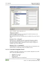
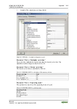
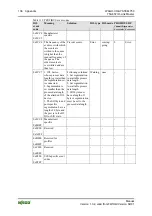
The entries of the file are displayed in the configuration software based on the
respective width of the process image (see the following figure).
Note the special data structure for PROFIBUS!
Pay attention to the special data structure for PROFIBUS:
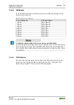
PROFIBUS supports a 2-byte Mailbox size. The process image is smaller by the
size of the Mailbox.
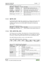
The GSD/GSE entry "75x-657 IOL-M 22 Byte PA P00" denotes a process image
of 24 bytes, the entry at set Mailbox size of 2 bytes.
Other GSD/GSE entries:
• "75x-657 IOL-M SIO-Mode PA P00"
PA of the IO-Link master 4 bytes
• "75x-657 IOL-M 4 Byte PA P00"
PA of the IO-Link master 6 bytes
• "75x-657 IOL-M 6 Byte PA P00"
PA of the IO-Link master 8 bytes
etc.
The correct process image size appears when you read the I/O module data using
WAGO-I/O-
CHECK
for example.
Figure 44: GSD/GSE entries
Observe the maximum number of I/O modules!
Due to the large volume of data (configuration data), max. 11 IO-Link masters
can be operated on a PROFIBUS fieldbus coupler in this variant P02.
For variant P00, max. 16 IO-Link masters can be operated on one PROFIBUS
fieldbus coupler.
11.4.1.2.1.1 Simple Configuration Record
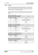
A simple configuration record P00 has the following parameters:
• Diagnosis
•
Port x > Diagnosis
•
Port x > Fragmentation


