16
Device Description
WAGO-I/O-SYSTEM 750
750-657 IO-Link Master
Manual
Version 1.0.2, valid from FW/HW-Version 02/01
Pos: 19 /Alle Serien (Allgemeine Module)/Überschriften für alle Serien/Gerätebeschreibung/Gerätebeschreibung - Überschrift 1 @ 3\mod_1233756084656_21.doc @ 27096 @ 1 @ 1
4 Device
Description
Pos: 20 /Serie 750 (WAGO-I/O-SYSTEM)/Gerätebeschreibung/Einleitung/Sonderklemmen/Gerätebeschreibung - Einleitung 750-0657 @ 5\mod_1253010532718_21.doc @ 41610 @ @ 1
The IO-Link Master 750-657 module is used to connect intelligent
actuators/sensors that the IO-Link communication system uses on the control
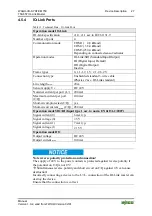
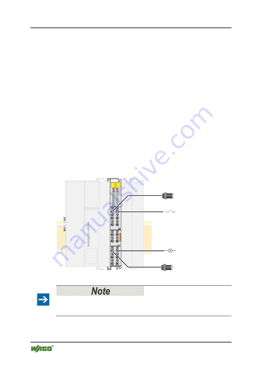
level. Using 3-wire connection technology, up to four IO-Link devices can be
connected to the individual ports of the IO-Link master.
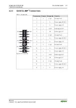
In addition to the two supply lines L+ and L-, there is another connection (C/Q)
used to transfer process, configuration, parameterization and diagnostic data. The
process data width of an IO-Link device can be between one bit (e.g. simple
switches) and 32 bytes (e.g. complex sensors/actuators).
Transfer is based on 24V levels. Transfer is half-duplex, i.e. data is sent and
received one after the other.
Standard sensor cables can be used. Shielding is not required.
WAGO-I/O-
CHECK
, function blocks or PROFIBUS-GSD/GSE can be used to
configure and parameterize the IO-Link master.
Two-color LEDs together with the status byte provide information about the
operating status of the individual IO-Link ports.
C/Q 1
C/Q 3
C/Q 2
C/Q 4
13
750-657
1
2
3
4
5
6
7
8
14
9
10
11
12
13
14
15
16
IO-Link device
Digital input
Digital output
IO-Link device
IO-Link master
Figure 2: Connection example: IO-Link master with various devices
Do not use IO-Link for safety-related applications!
In general, do not use IO-Link technology for safety-related applications, e.g.
emergency stop switch.
Pos: 21 /Dokumentation allgemein/Gliederungselemente/---Seitenwechsel--- @ 3\mod_1221108045078_0.doc @ 21810 @ @ 1

