WAGO-I/O-SYSTEM 750
Process Image
33
750-657 IO-Link Master
Manual
Version 1.0.2, valid from FW/HW-Version 02/01
Pos: 69 /Serie 750 (WAGO-I/O-SYSTEM)/Prozessabbild Klemmenbus/Sonderklemmen/Prozessabbild 750-0657 @ 5\mod_1253168052312_21.doc @ 41763 @ 1222233 @ 1
6 Process
Image
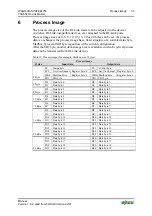
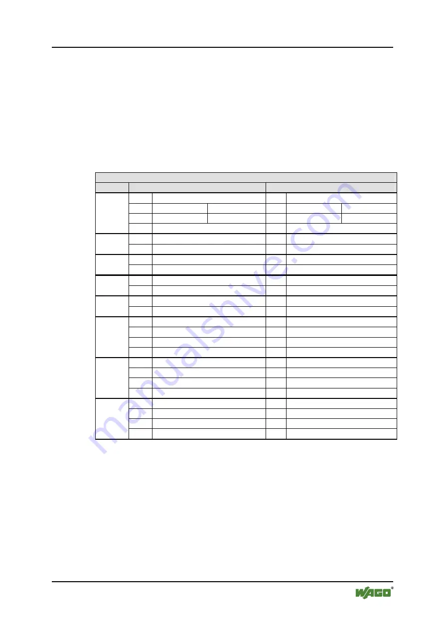
The process image size of the IO-Link master can be adjusted to the devices
(switches, IO-Link compatible devices, etc.) attached to the IO-Link ports.
Process image sizes of 4, 6, 8, 10, 12, 16, 20 or 24 bytes can be set. As process
data is exchanged, the process image has a fixed structure of a control/status byte,
Mailbox bytes and SIO byte regardless of the current configuration.
After the SIO byte, another data storage area is available in which cyclical process
data can be transferred from IO-Link devices.
Table 12: Process image (for example, Mailbox size 2 bytes)
Process image
Pi size
Input data
Output data
S0
Status byte
C0
Control byte
FC0
Acyclic channel Register byte 0
FC0 Acyclic channel Register byte 0
MB0 Mailbox-Byte
Register byte 1
MB0 Mailbox byte
Register byte 1
4 Byte
SIO
SIO byte
SIO SIO byte
D0
Data byte 0
D0
Data byte 0
6 Byte
D1
Data byte 1
D1
Data byte 1
D2
Data byte 2
D2
Data byte 2
8 Byte
D3
Data byte 3
D3
Data byte 3
D4
Data byte 4
D4
Data byte 4
10 Byte D5
Data byte 5
D5
Data byte 5
D6
Data byte 6
D6
Data byte 6
12 Byte D7
Data byte 7
D7
Data byte 7
D8
Data byte 8
D8
Data byte 8
D9
Data byte 9
D9
Data byte 9
D10
Data byte 10
D10 Data byte 10
16 Byte D11 Data byte 11
D11 Data byte 11
D12
Data byte 12
D12 Data byte 12
D13
Data byte 13
D13 Data byte 13
D14
Data byte 14
D14 Data byte 14
20 Byte D15 Data byte 15
D15 Data byte 15
D16
Data byte 16
D16 Data byte 16
D17
Data byte 17
D17 Data byte 17
D18
Data byte 18
D18 Data byte 18
24 Byte D19 Data byte 19
D19 Data byte 19


